Electromobile battery box and locking mechanism thereof

A technology for electric vehicles and locking mechanisms, which is applied to electric power units, power units, vehicle components, etc., can solve problems such as unreliable locking of lock heads

Active Publication Date: 2013-09-25
STATE GRID CORP OF CHINA +2
View PDF7 Cites 6 Cited by
  • Summary
  • Abstract
  • Description
  • Claims
  • Application Information

AI Technical Summary

Problems solved by technology

[0004] The purpose of the present invention is to provide a locking mechanism for the battery box of an electric vehicle, which is used to solve the problem of unreliable locking of the lock head caused by the use of positioning pins for locking and positioning of the lock head of the existing battery box locking mechanism; at the same time, the present invention The invention also provides a battery box using the locking mechanism

Method used


Image

  • Electromobile battery box and locking mechanism thereof
  • Electromobile battery box and locking mechanism thereof

Examples


Embodiment Construction

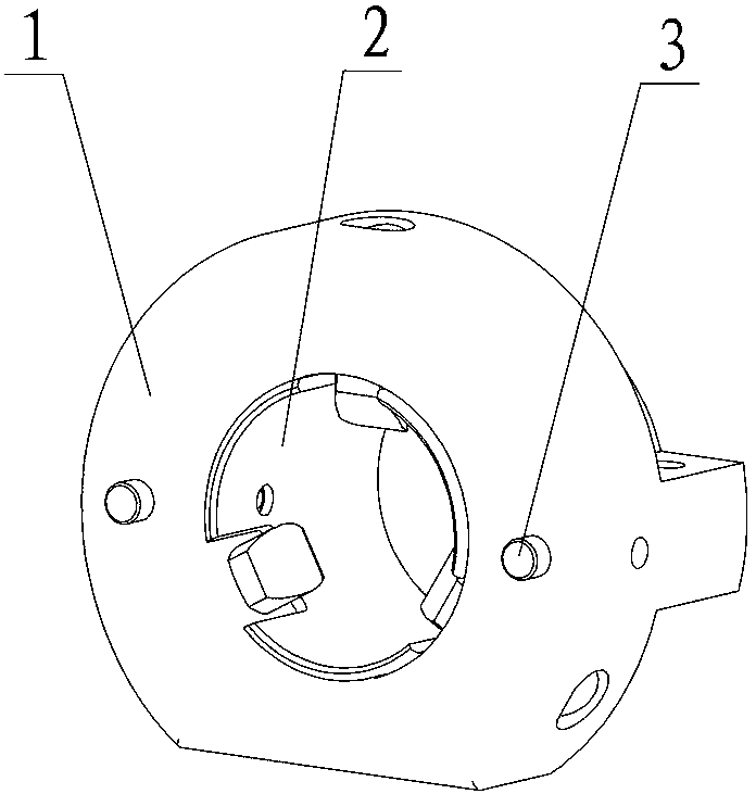
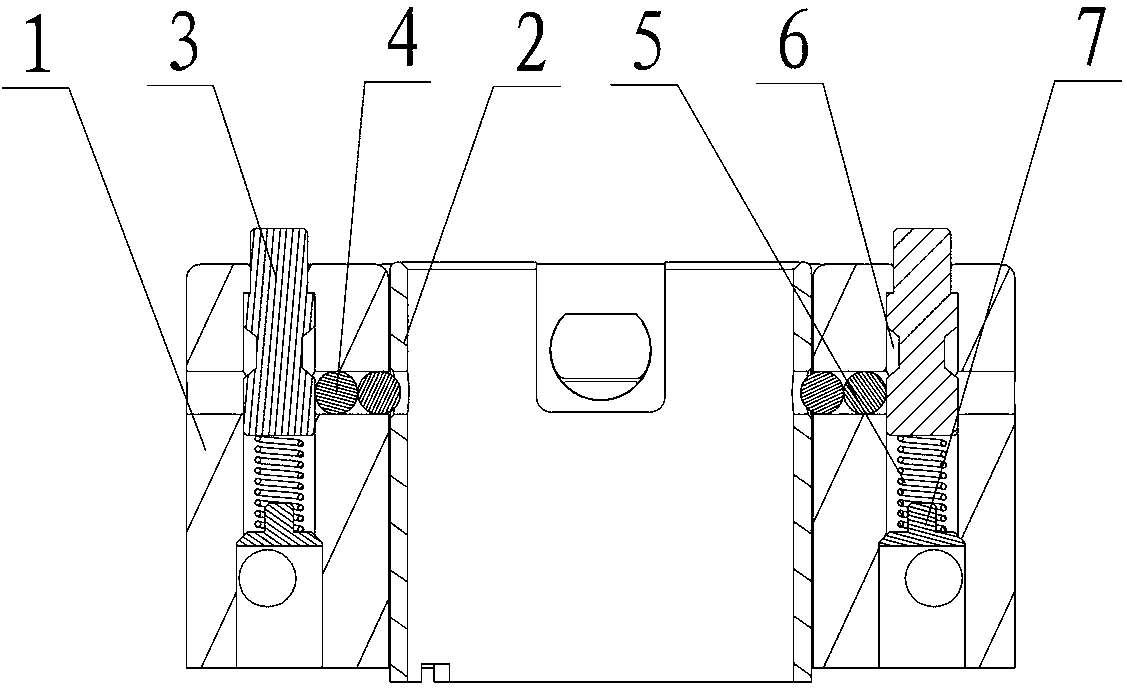
[0018] Embodiments of the battery box locking mechanism of the present invention: as figure 1 , figure 2 As shown, it includes the lock head 1 and the lock sleeve 2 axially inserted in the inner hole of the lock head for guiding the movement of the lock head 1 back and forth. The lock tongue (not shown in this part of the figure), the rear end of the lock sleeve 2 is used to be fixed on the front panel of the battery box, and the function of the lock head 1 is to drive the two The two lock tongues move correspondingly and are mated with the lock holes on the power box to realize the locking or unlocking of the battery box. Between the lock sleeve 2 and the lock head 1, there are two push-type self-locking units uniformly distributed along the circumference of the lock sleeve to realize the locking or unlocking of the lock head. The control shaft 3 on the surface, the control shaft 3 is a stepped shaft with a small front and a large rear. 1. The limit turning edge matched w...


PUM


Abstract

The invention discloses an electromobile battery box and a locking mechanism thereof. The locking mechanism comprises a lock head, a lock sleeve is mounted axially in an inner hole of the lock head in an inserted manner, press-type self-locking units are uniformly distributed along the circumferential direction of the lock head between the lock sleeve and the lock head, each self-locking unit comprises a control shaft connected on the front end face of the lock head in an axial limiting moving inserted manner, and a stopper assembled between the control shaft and the lock sleeve, a locking recessed portion allowing the corresponding end portion of the stopper to be clamped in and mounted between the lock sleeve and the control shaft in an ejected manner to realize locking of the lock head when the control shaft moves forwards to a locking position is arranged on the peripheral face of the lock sleeve, an unlocking groove allowing the corresponding end portion of the stopper to enter to enable the stopper to be capable of being radially separated from the locking recessed portion when the control shaft moves backwards to an unlocking position is formed on the peripheral face of the control shaft, and a resetting elastic member applying a forward acting force on the control shaft to prevent the same to be unlocked is arranged between the control shaft and the lock head. The locking mechanism and the electromobile battery box using the same have the advantages of convenience in operation and stable locking effect.

Description

technical field [0001] The invention relates to an electric vehicle battery box and a locking mechanism thereof. Background technique [0002] The battery box of an electric vehicle is the energy supply part of the electric vehicle. The mileage and service life of the electric vehicle are closely related to the life of the battery box. Especially in the process of driving the electric vehicle, the stability and safety of the battery box are particularly important. [0003] Chinese patent document C202242929U discloses a locking mechanism for a battery box and a battery box using the locking mechanism. The locking mechanism is arranged on the front panel of the battery box, and its lock head is guided along the push-pull direction of the battery box in and out of the power compartment. It is mobile assembled on the battery box, and the two sides of the lock head are respectively connected to the lock tongue moving along the left and right direction of the battery box through ...

Claims


Application Information

Patent Timeline
Patent Type & Authority Applications(China)
IPC IPC(8): B60K1/04
Inventor 张永峰朱云霄郭炎杰郭胜军李山吕志娟张焕德李明明刘乙力窦辉杨俊华鲁晓强
Owner STATE GRID CORP OF CHINA
Why Eureka
Try Eureka