Wire clamping and conveying device
A technology of clamping, conveying and conducting wires, applied in the directions of circuit/collector parts, electrical components, circuits, etc., can solve the problems of affecting the collection of wires, troublesome processing and production, and easy winding of wires on the machine, so as to avoid winding on the machine. The effect of convenient production and processing
- Summary
- Abstract
- Description
- Claims
- Application Information
AI Technical Summary
Problems solved by technology
Method used
Image

Examples
Embodiment Construction
[0009] The present invention will be further described below in conjunction with the accompanying drawings.
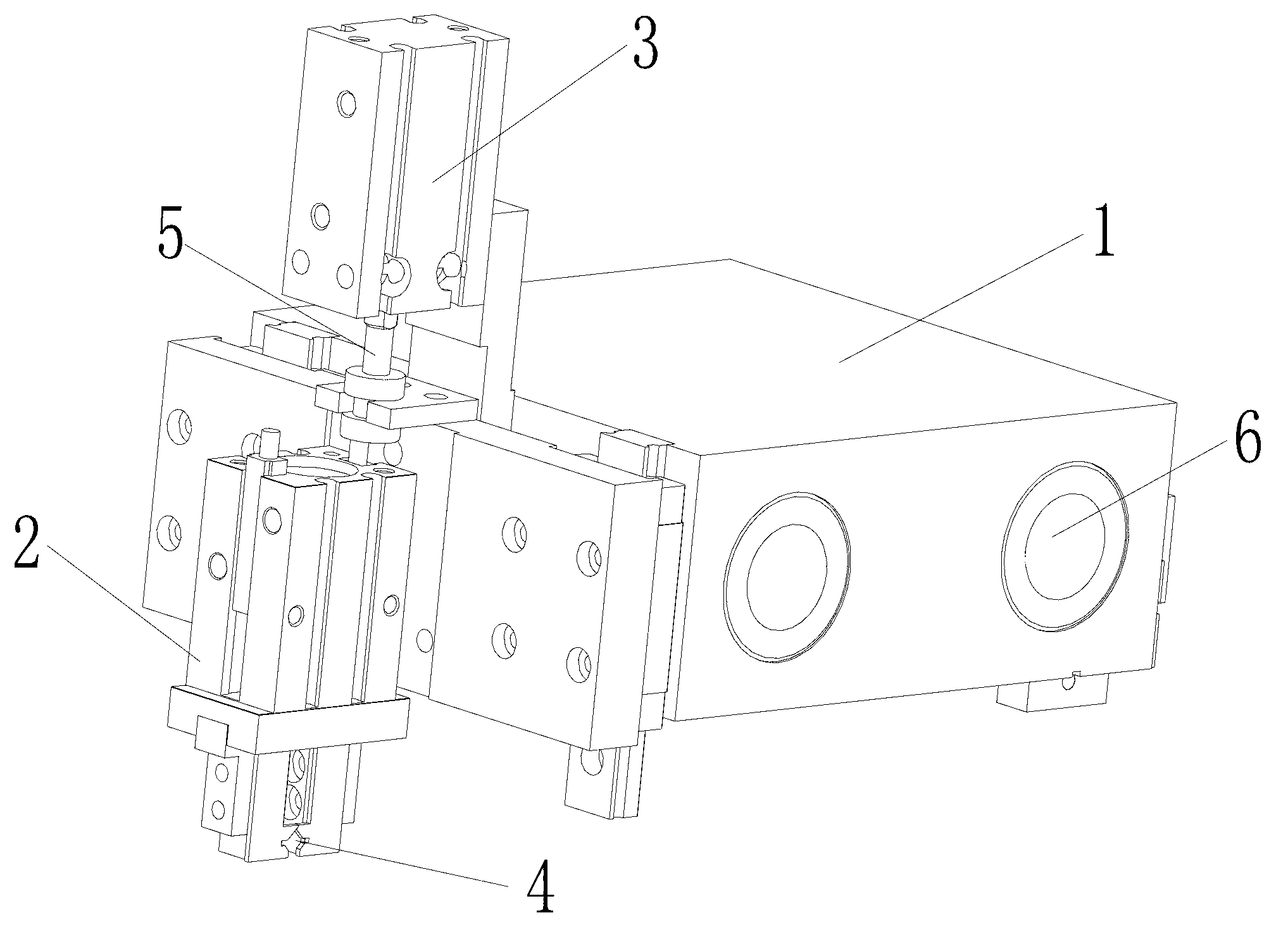
[0010] Such as figure 1 As described above, a wire clamping and conveying device includes a sliding seat 1, a moving block 2, an air cylinder 3 and jaws 4, and two through holes 6 for passing through guide rails are arranged on the sliding seat 1, and on the sliding seat 1 A cylinder 3 is connected to the side of the side that is not provided with the through hole 6, and the cylinder rod 5 of the cylinder 3 is connected to the moving block 2 provided below the cylinder 3, and the bottom of the moving block 2 is provided with a jaw 4. The cylinder adopts a linear guide cylinder.
[0011] The cylinder rod 5 of the cylinder 3 of the wire clamping and conveying device of the present invention is connected to the moving block 2 arranged below the cylinder 3, and the bottom of the moving block 2 is provided with a gripper 4, which can better hold the wire through the grippe...
PUM
 Abstract
Description
Claims
Application Information
 - R&D
- Intellectual Property
- Life Sciences
- Materials
- Tech Scout
- Unparalleled Data Quality
- Higher Quality Content
- 60% Fewer Hallucinations
Browse by: Latest US Patents, China's latest patents, Technical Efficacy Thesaurus, Application Domain, Technology Topic, Popular Technical Reports.
© 2025 PatSnap. All rights reserved.Legal|Privacy policy|Modern Slavery Act Transparency Statement|Sitemap|About US| Contact US: help@patsnap.com