O-shaped rotary engine

A rotary engine and engine technology, applied to combustion engines, machines/engines, internal combustion piston engines, etc., can solve problems such as low energy conversion efficiency, loss of mechanical energy, and high noise, and achieve high energy conversion efficiency, easy processing and production, The effect of high combustion efficiency

Inactive Publication Date: 2012-07-18
彭超
View PDF7 Cites 1 Cited by
  • Summary
  • Abstract
  • Description
  • Claims
  • Application Information

AI Technical Summary

Problems solved by technology

The reciprocating piston engine has a simple structure and is easy to expand, but it has several disadvantages: First, it relies on the inertia of the flywheel to maintain the continuity between each stroke, resulting in the need to install a heavy flywheel and reduce the engine's capacity. power to weight ratio
Second, the detonation and detonation work time of the fuel is short, so part of the fuel is discharged before being fully burned, resulting in low fuel combustion efficiency
Third, it needs to convert the reciprocating motion of the piston into the rotation of the power shaft through the crankshaft, in which part of the mechanical energy will be lost
Fourth, when the crankshaft rotates, the center of gravity shifts, causing the whole machine to vibrate greatly, and the noise is also large
But it also has several disadvantages: First, it needs to rely on complex mechanical devices to convert the motion of the triangular rotor around the power shaft into the rotation of the power shaft, which is not conducive to assembly and maintenance
Second, its triangular rotor needs to move in a cylinder with a special shape. The special shape of the cylinder

Method used


Image

  • O-shaped rotary engine
  • O-shaped rotary engine
  • O-shaped rotary engine

Examples


Example Embodiment

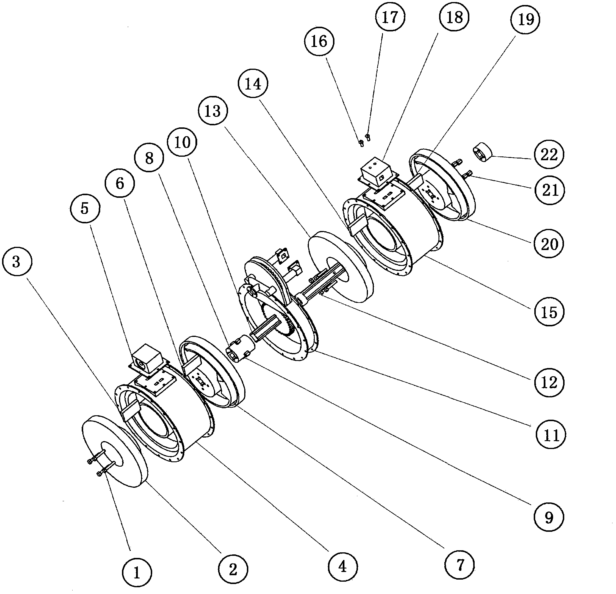
[0037] Structural features of O-type rotary engine:

[0038] Such as figure 1 Shown. Compressor rotor fastening screws (1), compressor inner rail rotor (2), compressor inner diaphragm (3), compressor stator (4), compressor outer diaphragm (6), compressor outer rail rotor ( 7), compressor rotor fastening nut (9) and power machine rotor fastening screw (12), power machine rotor (13), power machine inner diaphragm (14), power machine stator (15), power machine outer diaphragm (19) The outer rail rotor (20) of the power machine and the fastening nut (21) of the power machine rotor have the same structure. In the specific implementation, the volume of the compressor should be greater than or equal to the volume of the power machine, and the volume of the compressor is larger than the volume of the power machine , The higher the compression ratio of fuel and air mixture at the moment of ignition. Compressor and power machine are made of such Figure 2A , Figure 2B , Figure 2C The i...


PUM


Abstract

An O-shaped rotary engine comprises a gas compressor, a power machine, a flow divider, a gas compressor flow guide and a power shaft. The gas compressor and the power machine have same structures, namely both comprise an I-shaped annular stator with two partition guide holes staggered outside and inside in a middle partitioned portion, and both are provided with two rotors at two ends and comprising trapezoid-like protrusions (pistons) extending into an annular groove, wherein one rotor comprises an outer guide rail while the other rotor comprises an inner guide rail, and the outer guide rail and the inner guide rail respectively clamp a partition with the corresponding pistons and the two lateral annular faces of each piston to enable the partition to axially reciprocate in the partition guide holes to partition the annular groove into two portions with high air tightness. By means of mutual cooperation of all portions of the engine, continuous blasting to directly output shaft work can be realized, and four stokes are completed simultaneously in different cavities. The O-shaped rotary engine is large in power-weight ratio, low in vibration, high in energy conversion efficiency, simple in structure and easy in processing and manufacturing and can be used as an aeroengine.

Description

Technical field: [0001] The invention relates to an internal combustion engine which directly outputs shaft power, in particular to a rotary engine with simple structure, small vibration, high power-to-weight ratio and high efficiency. Background technique: [0002] At present, there are mainly three types of engines that output shaft power that are put into practical application: reciprocating piston engines, triangular rotor engines, and gas turbine shaft engines. The reciprocating piston engine has a simple structure and is easy to expand, but it has several disadvantages: First, it relies on the inertia of the flywheel to maintain the continuity between each stroke, resulting in the need to install a heavy flywheel and reduce the engine's capacity. power to weight ratio. The second, its fuel detonation work time is short so that part of the fuel is discharged without fully burning, resulting in low fuel combustion efficiency. Third, it needs to convert the reciprocatin...

Claims


Application Information

Patent Timeline
IPC IPC(8): F02B53/00F02B53/08
CPCY02T10/17Y02T10/12
Inventor 彭超
Owner 彭超
Why Eureka
Try Eureka