Uplink power control method, network node and system
A network node and power control technology, applied in the field of communication, can solve problems such as insufficient uplink transmission power
- Summary
- Abstract
- Description
- Claims
- Application Information
AI Technical Summary
Problems solved by technology
Method used
Image
Examples
Embodiment 1
[0034] This embodiment provides an uplink power control method, such as figure 1 As shown, the method includes:
[0035] 101. The first network node sends a first indication message to a second network node, where the first indication message includes a time pattern and / or a maximum transmission power of a user equipment UE performing uplink transmission on the second network node, wherein, The time pattern is used to control the transmission time of the UE for uplink transmission.
[0036] Optionally, before the first network node sends the first indication message to the second network node, the method further includes: the first network node receiving a second indication message sent by the UE, the second The indication message is used to indicate that the uplink data buffered by the UE to be sent to the second network node exceeds a first predetermined threshold; the first network node determines that the UE performs uplink transmission on the second network node The tim...
Embodiment 2
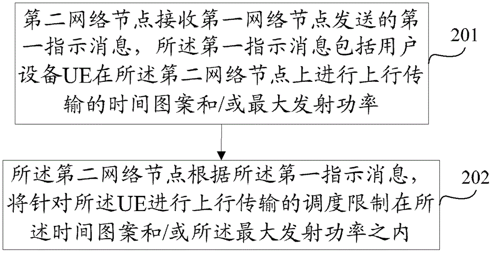
[0047] This embodiment provides an uplink power control method, such as figure 2 As shown, the method includes:
[0048] 201. The second network node receives a first indication message sent by a first network node, where the first indication message includes a time pattern and / or a maximum transmit power of a user equipment UE performing uplink transmission on the second network node.
[0049] 202. The second network node limits the scheduling of uplink transmission for the UE within the time pattern and / or the maximum transmission power according to the first indication message.
[0050] Optionally, before the second network node receives the first indication message sent by the first network node, the method further includes: the second network node receiving a second indication message sent by the UE, the first The two indication messages are used to indicate that the uplink data cached by the UE to be sent to the second network node exceeds a first predetermined thresho...
Embodiment 3
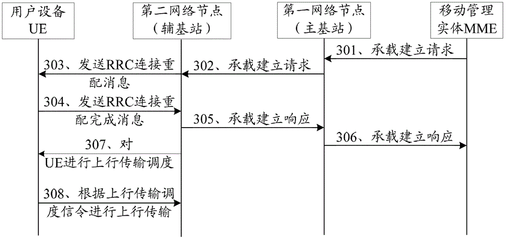
[0057] This embodiment provides an uplink power control method, the first network node is the primary base station, and the second network node is the secondary base station, for example image 3 As shown, the method includes:
[0058] 301. An MME (Mobility Management Entity, mobility management entity) sends a bearer establishment request to a master base station.
[0059] The bearer establishment request includes the UE corresponding to the bearer to be created and the service requirement information of the bearer.
[0060] Optionally, the MME may also send a bearer deletion request or a bearer modification request to the master base station.
[0061] 302. The primary base station determines a secondary base station to establish the new bearer, and sends a bearer establishment request to the secondary base station.
[0062] Specifically, after receiving the bearer establishment request, the primary base station decides which secondary base station to establish the radio be...
PUM
 Abstract
Description
Claims
Application Information
 - R&D
- Intellectual Property
- Life Sciences
- Materials
- Tech Scout
- Unparalleled Data Quality
- Higher Quality Content
- 60% Fewer Hallucinations
Browse by: Latest US Patents, China's latest patents, Technical Efficacy Thesaurus, Application Domain, Technology Topic, Popular Technical Reports.
© 2025 PatSnap. All rights reserved.Legal|Privacy policy|Modern Slavery Act Transparency Statement|Sitemap|About US| Contact US: help@patsnap.com


