
Gate drive circuit

A gate drive circuit and circuit technology, applied in instruments, static indicators, etc., can solve the problems of pixel flicker, increased circuit power consumption, and inconvenience.

Inactive Publication Date: 2013-10-02
CPT TECH GRP +1
View PDF10 Cites 1 Cited by
  • Summary
  • Abstract
  • Description
  • Claims
  • Application Information

AI Technical Summary

Problems solved by technology

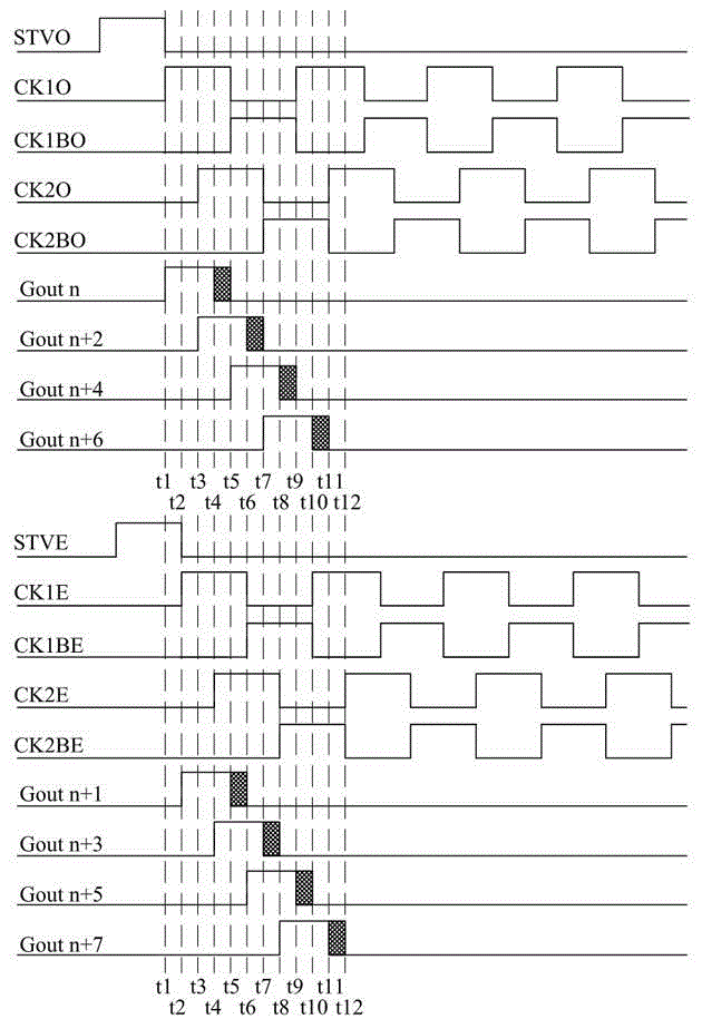
It can be clearly seen from Figure 1 that the output signal Gout(n) overlaps with the output signal Gout(n+2). In detail, if referring to the output signal Gout(n) and the output signal Gout(n+1 ), nearly three-quarters of the parts overlap, which will cause the pixels to flicker, and in addition, the power consumption of the circuit will also increase
[0004] This shows that above-mentioned existing mode obviously still has inconvenience and defective, and needs to be improved
In order to solve the above problems, related fields have tried their best to find a solution, but a suitable solution has not been developed for a long time.

Method used


Image

  • Gate drive circuit
  • Gate drive circuit
  • Gate drive circuit

Examples


Embodiment Construction

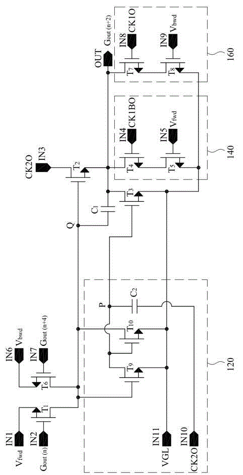
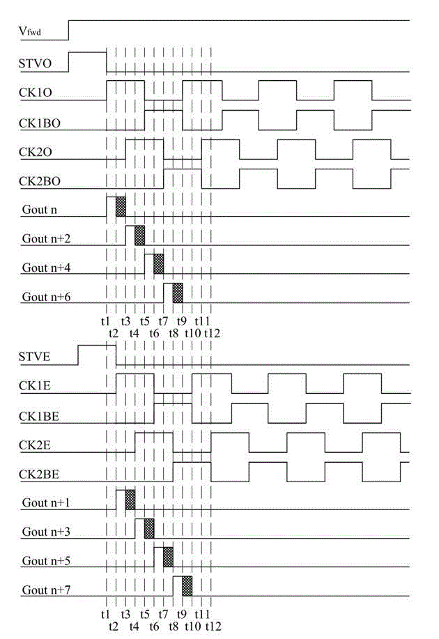
[0062] First, please refer to figure 1, which is a schematic diagram illustrating an operation waveform of a conventional gate driving circuit according to an embodiment of the present invention. As shown in the figure, the output signals Gout(n) and Gout(n+1) of the nth stage and the n+1th stage circuit in the conventional gate drive circuit overlap, and the overlapping part accounts for the output signal Nearly three quarters, if the time t1 to t2 is taken as a time unit, the above-mentioned overlapping part accounts for three units. In order to solve the problem of overlapping output signals between the gate drive circuit stages of the gate drive circuit, the embodiment of the present invention proposes an innovative circuit structure in order to improve the phenomenon of pixel flicker and high power consumption of the circuit. This circuit structure As shown in FIG. 2 , it is a schematic diagram illustrating a gate driving circuit according to an embodiment of the present...


PUM


Abstract

The invention relates to a gate drive circuit. The drive circuit comprises a first input terminal, a second input terminal, a third input terminal, an output terminal, a first transistor, a second transistor, a third transistor, a voltage stabilizing circuit, a capacitor and a pull-down circuit. A first end of the first transistor is coupled with the first input terminal, and a control terminal of the transistor is coupled with the second input terminal; a first terminal of the second transistor is coupled with the third input terminal, a control terminal of the second transistor is coupled with a second terminal of the first transistor, and a second terminal of the second transistor is coupled with the output terminal; a first terminal of the third transistor is coupled with the output terminal, and a second terminal of the third transistor is coupled with a grounding terminal; the capacitor is coupled between the control terminal of the second transistor and the output terminal; and the pull-down circuit is coupled with the output terminal and the grounding terminal.

Description

technical field [0001] The present invention relates to a gate drive circuit structure, and in particular to a gate drive circuit in a panel. Background technique [0002] With the advancement of technology, consumers have increasing demands on the resolution of liquid crystal displays, and in order to manufacture high-resolution liquid crystal displays, the industry gradually adopts a configuration method of gate-in-panel circuits. [0003] For example, in an eight-stage circuit structure adopting bidirectional scanning, the output signal provided by it is shown in FIG. 1 . It can be clearly seen from Figure 1 that the output signal Gout(n) overlaps with the output signal Gout(n+2). In detail, if referring to the output signal Gout(n) and the output signal Gout(n+1 ), nearly three-quarters of the parts overlap, which will cause the pixels to flicker, and in addition, the power consumption of the circuit will also increase. [0004] This shows that above-mentioned existing...

Claims


Application Information

Patent Timeline
IPC IPC(8): G09G3/36
Inventor 李威龙赖枝文
Owner CPT TECH GRP
Learn More