Rotary overhead operation scaffold

A high-altitude operation and rotary technology, applied in the direction of overhead lines/cable equipment, etc., can solve the problems that the industrial control console cannot be moved and is inconvenient to use

Inactive Publication Date: 2013-10-02
STATE GRID CORP OF CHINA +1
View PDF5 Cites 2 Cited by
  • Summary
  • Abstract
  • Description
  • Claims
  • Application Information

AI Technical Summary

Problems solved by technology

[0004] The purpose of the present invention is to solve the problem that the industrial control console cannot be moved and is inconvenient to use, so as to provide

Method used


Image

  • Rotary overhead operation scaffold

Examples


Embodiment Construction

[0014] The technical solutions of the present invention will be described in further detail below through specific implementation methods.

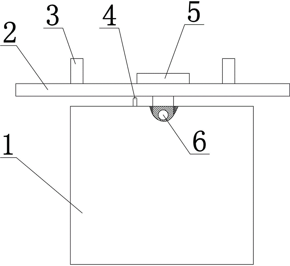
[0015] Such as figure 1 As shown, a rotary aerial work platform includes a hook device with a platform body 1 arranged above the platform body 1. The hook device includes a cross bar 2 and a hook 3 fixedly connected to the upper end of the cross bar 2. The hook 3 There are at least two, the hook 3 is provided with a lock, the crossbar 2 is rotatably connected with the stand body 1 through the rotating bolt 5, the crossbar 2 is provided with handrails, the stand body 1 is provided with a screw hole, and the side of the screw hole is provided There are fixing holes 6, connecting holes are provided at the corresponding positions on the cross bar 2, the rotating bolts 5 pass through the connecting holes and screwed into the screw holes, and the fixing holes 6 correspond to the holes on the rotating bolts 5, and the two are fixed with pins . ...


PUM


Abstract

The invention provides a rotary overhead operation scaffold. The rotary overhead operation scaffold comprises a scaffold body and a hooking device arranged above the scaffold. The hooking device includes a cross bar and hooks fixedly connected at an upper end of the cross bar, wherein the number of the hooks is at least two, and the cross bar is rotationally connected with the scaffold body. The rotary overhead operation scaffold has the advantages of scientific design, simple structure, convenient operation and high safety, and rotation angles of the scaffold are controllable.

Description

technical field [0001] The invention relates to a platform for aerial work, in particular to a rotating platform for aerial work. Background technique [0002] The known high-altitude operating platform operates on a cross arm suspended on the wire pole, and the position is fixed and cannot be moved. Some special positions cannot be touched by the staff standing on the operating platform, and cannot meet various work needs. [0003] In order to solve the above existing problems, people have been seeking an ideal technical solution. Contents of the invention [0004] The purpose of the present invention is to solve the problem that the industrial control console cannot be moved and is inconvenient to use, so as to provide a rotary aerial work platform with scientific design, simple structure, rotatable platform, controllable rotation angle, convenient operation and high safety shelf. [0005] In order to achieve the above object, the technical solution adopted by the pres...

Claims


Application Information

Patent Timeline
IPC IPC(8): H02G1/02
Inventor 彭祖华易瑾
Owner STATE GRID CORP OF CHINA
Why Eureka
Try Eureka