Power distribution network reactive compensation node sorting method based on second-order transmission loss sensitivity matrix

A network loss sensitivity and sensitivity technology, applied in the field of electric power information

Active Publication Date: 2015-04-22
杭州东华电力设备有限公司
View PDF2 Cites 0 Cited by
  • Summary
  • Abstract
  • Description
  • Claims
  • Application Information

AI Technical Summary

Problems solved by technology

[0036] Aiming at the problem that it is difficult to consider the influence of the post-compensation node on the front-compensation node when reactive power is optimized and selected for reactive power compensation in the distribution network, the present invention proposes a calculation method of the second-order network loss sensitivity matrix, and uses the second-order network loss sensitivity matrix to calculate The new method of modifying the sensitivity for reactive power optimization planning of distribution network makes the selection of reactive power compensation point more reasonable, the compensation scheme is more economical, further reduces network loss, improves voltage level and power factor, and greatly improves the distribution network. The reactive power optimization has high theoretical significance and application value

Method used


Image

  • Power distribution network reactive compensation node sorting method based on second-order transmission loss sensitivity matrix
  • Power distribution network reactive compensation node sorting method based on second-order transmission loss sensitivity matrix
  • Power distribution network reactive compensation node sorting method based on second-order transmission loss sensitivity matrix

Examples


Embodiment Construction

[0047] The present invention will be further described below in conjunction with accompanying drawing.

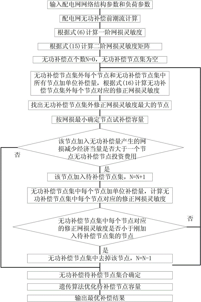
[0048] a. Reference figure 1 , the reactive power optimization of the present invention follows the steps:

[0049] b. Step (1): Establish a reactive power optimization model of the distribution network:

[0050]

[0051] In the formula: is the active power price of the system; is the active loss; is the operating time at this load level, is the reactive power compensation capacity of node i; is the unit price of reactive power compensation capacity; is the depreciation maintenance rate of the reactive power compensation device; is the return on investment of the reactive power compensation device; , are the penalty factor for voltage exceeding the limit and the penalty factor for reactive power exceeding the limit; ( , ) is the upper or lower limit of the voltage or reactive state variable, when hour, ;when hour, ,when when, take .

...


PUM


Abstract

The invention discloses a power distribution network reactive compensation node sorting method based on a second-order transmission loss sensitivity matrix. The method comprises the steps of firstly, calculating a first-order transmission loss sensitivity and second-order transmission loss sensitivity matrix, and calculating reactive to-be-compensated node-set external node transmission loss reactive correction sensitivity according to the first-order transmission loss sensitivity and second-order transmission loss sensitivity matrix; secondly, sequentially finding out the node with the largest reactive to-be-compensated node-set external node transmission loss reactive correction sensitivity; then, adding reactive compensation capacity at the node, wherein the reactive compensation capacity enables the transmission loss to be the minimum, and the reactive compensation capacity is used as the amount to be compensated, and judging whether the transmission power reduction economic equivalent amount at the moment is larger than the investment cost of the node; finally, judging whether the power transmission loss reactive correction sensitivity of each node is smaller than the transmission loss reactive correction sensitivity of a node which is just added into the reactive to-be-compensated node set. According to the power distribution network reactive compensation node sorting method based on the second-order transmission loss sensitivity matrix, the nonlinear factors of changes of network tides after the compensation is added are considered, and the influences caused by a previous compensation node on a later compensation node are also considered. According to the compensation scheme, the reduction of the system transmission loss is more, investment is little, and economical performance is better.

Description

technical field [0001] The invention belongs to the technical field of electric power information, and relates to a method for selecting reactive power compensation points of a distribution network based on a second-order network loss sensitivity matrix. Background technique [0002] Due to historical reasons, there has been a large power gap for a long time in our country. Therefore, the construction of power sources is obviously stronger than the construction of power grids. The problem of active power dispatching is emphasized while the problem of reactive power dispatching is ignored, especially the reactive dispatching of distribution networks. , causing a large amount of reactive power to flow in the distribution network, which not only increases the active power loss of the distribution network, but also affects the voltage quality of the distribution network. At present, the power sector has gradually paid more attention to the problem of reactive power compensation ...

Claims


Application Information

Patent Timeline
Patent Type & Authority Patents(China)
IPC IPC(8): H02J3/18G06F19/00
CPCY02E40/30
Inventor 高慧敏尚群立江力余再兴
Owner 杭州东华电力设备有限公司
Why Eureka
Try Eureka