
A Cube Magnet Pushing Mechanism Based on Halbach Permanent Magnet Array

A technology of pushing mechanism and permanent magnet array, which is applied in the manufacture of stator/rotor body, etc., can solve the problems of time-consuming manual bonding, poor precision and low efficiency, and achieve the effect of efficient manufacturing process, reasonable design and convenient operation.

Inactive Publication Date: 2016-05-25
UNIV OF ELECTRONICS SCI & TECH OF CHINA
View PDF7 Cites 0 Cited by
  • Summary
  • Abstract
  • Description
  • Claims
  • Application Information

AI Technical Summary

Problems solved by technology

However, there are various problems in manual bonding: 1. Low efficiency; 2. High risk; 3. The glue used for bonding has a pungent smell, which will damage the respiratory tract of workers; 4. High error rate
[0003] Aiming at the problems of time-consuming manual bonding, low efficiency, poor precision, dangerous working environment, and easy injury of personnel in the bonding of permanent magnetic array magnetic steel, an automatic solution is proposed

Method used


Image

  • A Cube Magnet Pushing Mechanism Based on Halbach Permanent Magnet Array
  • A Cube Magnet Pushing Mechanism Based on Halbach Permanent Magnet Array
  • A Cube Magnet Pushing Mechanism Based on Halbach Permanent Magnet Array

Examples


Embodiment Construction

[0019] Below in conjunction with specific embodiment, further illustrate the present invention.

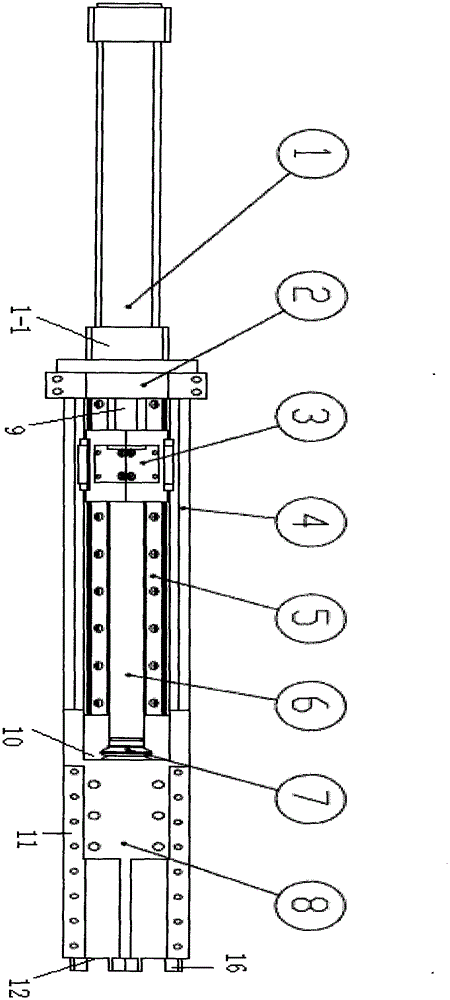
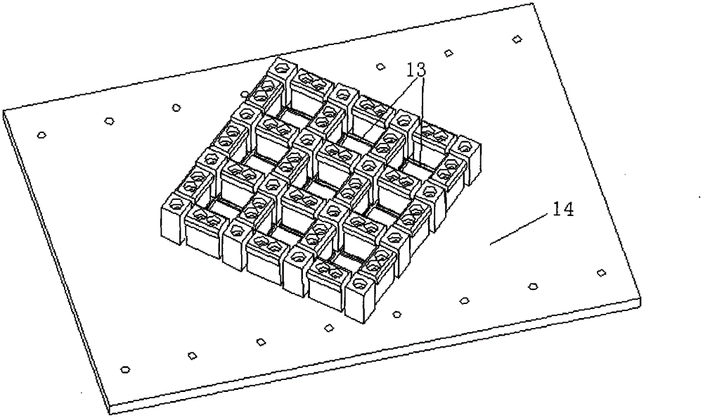
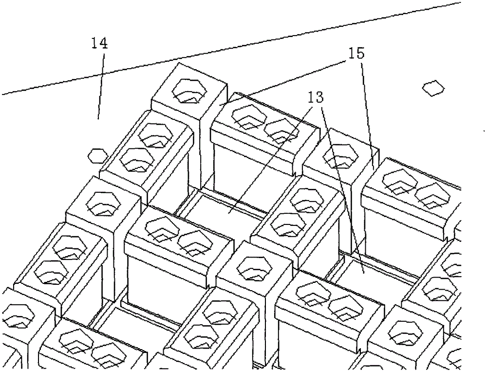
[0020] Such as Figure 1-3 Shown: a cube magnetic steel push mechanism, which sequentially includes a power supply part, a guide rail buffer part and a magnetic steel push channel, is characterized in that,

[0021] The power supply part includes a cylinder (1), a cylinder block (1-1) and a cylinder mounting plate (2);

[0022] The buffer part of the guide rail includes a slider (3), a sleeve (4), a guide rail (5), a push rod (6), a cylinder push rod (9) and a buffer suction cup (7);

[0023] The magnetic steel push channel includes a magnetic steel inlet (10), a sleeve front cover (8), a sleeve front end (11) and a magnetic steel push outlet (12);

[0024] The cylinder (1) is connected to the cylinder push rod (9) through the cylinder block (1-1) and the cylinder mounting plate (2), and the cylinder push rod (9) passes through the slide block (3) and the ejector rod (6) ), the...


PUM


Abstract

The invention relates to a cube magnetic steel pushing mechanism based on a Halbach permanent magnet array. The cube magnetic steel pushing mechanism sequentially comprises a power supplying part, a guide rail buffering part and a magnetic steel pushing channel. The cube magnetic steel pushing mechanism is simple in structure, reasonable in design and convenient to operate, achieves loading, pushing and final placing of magnetic steel, and enables the manufacturing process of the whole permanent magnet array to be much efficient, much stable and safer.

Description

technical field [0001] The invention relates to a cube magnetic steel pushing mechanism. Background technique [0002] At present, there is little discussion on the manufacturing process of the Halbach permanent magnet array. After investigation, the permanent magnet array is still bonded manually with tooling. However, there are various problems in manual bonding: 1. Low efficiency; 2. High risk; 3. The glue used for bonding has a pungent smell, which will damage the respiratory tract of workers; 4. The error rate is high. The present invention aims to solve these problems, cooperate with the whole equipment, realize the automatic operation of magnetic steel bonding, and pave the way for automatic production. [0003] Aiming at the problems of time-consuming manual bonding, low efficiency, poor precision, dangerous working environment, and easy injury of personnel in the bonding of permanent magnetic array magnetic steel, an automatic solution is proposed. [0004] This s...

Claims


Application Information

Patent Timeline
Patent Type & Authority Patents(China)
IPC IPC(8): H02K15/03
Inventor 徐振源彭倍秦东兴
Owner UNIV OF ELECTRONICS SCI & TECH OF CHINA
Learn More