
Clamping device

A technology of clamping equipment and clamping parts, which is applied in the direction of workpiece clamping devices and manufacturing tools, can solve the problems of high cost, inability to achieve two-way, slipping or distortion, etc., and achieve the effect of low cost and simple structure

Active Publication Date: 2015-05-27
烽禾升医疗设备(昆山)有限公司
View PDF5 Cites 0 Cited by
  • Summary
  • Abstract
  • Description
  • Claims
  • Application Information

AI Technical Summary

Problems solved by technology

[0002] Most of the clamping equipment on the market is one-way clamping equipment, which cannot be bidirectional, which makes the workpiece easy to slip during the clamping process; there are also some bidirectional clamping mechanisms in the prior art, but they must be in the clamping direction. Place a source of power on each side, for example, if clamping in the X and Y directions, it is necessary to install a clamping cylinder in the X direction and a cylinder in the Y direction, which is costly and difficult to do because of the huge mechanism. The clamping parts in the X and Y directions are clamped synchronously, and the clamping force must be controlled. If the force is not equal, it will cause instability such as slipping or distortion, and it is not conducive to control

Method used


Image

  • Clamping device

Examples


Embodiment

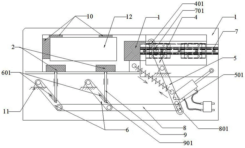
[0023] Embodiment: the cylinder drives the second guide rod, changes the angle relative to the slide rail 7 and moves the second guide rod upward, thereby driving the first guide rod to move upward, and the first slide groove 401 is inclined to the slide rail 7, so that the slide rail 7 Move toward the workpiece 12 to clamp the workpiece 12; the second guide rod drives the connecting rod 8 to move upward, thereby driving the third guide rod upward, and the third chute 601 is inclined to the guide rod 9, so that the guide rod 9 presses the workpiece 12 upward ; So as to achieve the purpose of two-way efficient clamping workpiece 12.


PUM


Abstract

The invention discloses a clamping device which comprises a base, workpiece positioners arranged between the base and a workpiece and used for positioning the clamping location of the workpiece, clamping pieces which are used for clamping the workpiece and comprise an X clamping piece and a Y clamping piece, a guiding device used for connecting the clamping pieces and guiding the movement direction of the clamping piece, a returning piece connected with the guiding device and a driving piece connected with the guiding device; the driving piece comprises an X guiding piece used for guiding the X clamping piece and a Y guiding piece used for guiding the Y clamping piece. The clamping device needs only one power source to realize bidirectional clamping, has a simple structure and is low in cost.

Description

technical field [0001] A clamping device, in particular a bi-directional clamping device. Background technique [0002] Most of the clamping equipment on the market is one-way clamping equipment, which cannot be bidirectional, which makes the workpiece easy to slip during the clamping process; there are also some bidirectional clamping mechanisms in the prior art, but they must be in the clamping direction. Place a source of power on each side, for example, if clamping in the X and Y directions, it is necessary to install a clamping cylinder in the X direction and a cylinder in the Y direction, which is costly and difficult to do because of the huge mechanism. The clamping parts in the X and Y directions are clamped synchronously, and the clamping force must be controlled. If the force is not equal, it will cause instability such as slipping or distortion, which is not conducive to control. Contents of the invention [0003] In order to solve the deficiencies of the prior...

Claims


Application Information

Patent Timeline
Patent Type & Authority Patents(China)
IPC IPC(8): B25B11/00
Inventor 郁金德
Owner 烽禾升医疗设备(昆山)有限公司
Learn More