
Multifunctional tool chuck for numerical control vertical lathe

A CNC vertical lathe and multi-functional technology, applied in the direction of tool clamps, etc., can solve the problems of complex structure of the main engine part of the steam turbine, and achieve the effects of being convenient for wide-scale use, simple in structure and cost-saving.

Inactive Publication Date: 2015-04-08
HARBIN TURBINE
View PDF6 Cites 0 Cited by
  • Summary
  • Abstract
  • Description
  • Claims
  • Application Information

AI Technical Summary

Problems solved by technology

[0003] The purpose of the present invention is to solve the problem that due to the complex structure of the steam turbine main engine part, the toolholder needs to be replaced continuously during processing, and there is no special multifunctional toolholder for CNC vertical lathe, and to provide a multifunctional toolholder for CNC vertical lathe

Method used


Image

  • Multifunctional tool chuck for numerical control vertical lathe
  • Multifunctional tool chuck for numerical control vertical lathe
  • Multifunctional tool chuck for numerical control vertical lathe

Examples


specific Embodiment approach 1

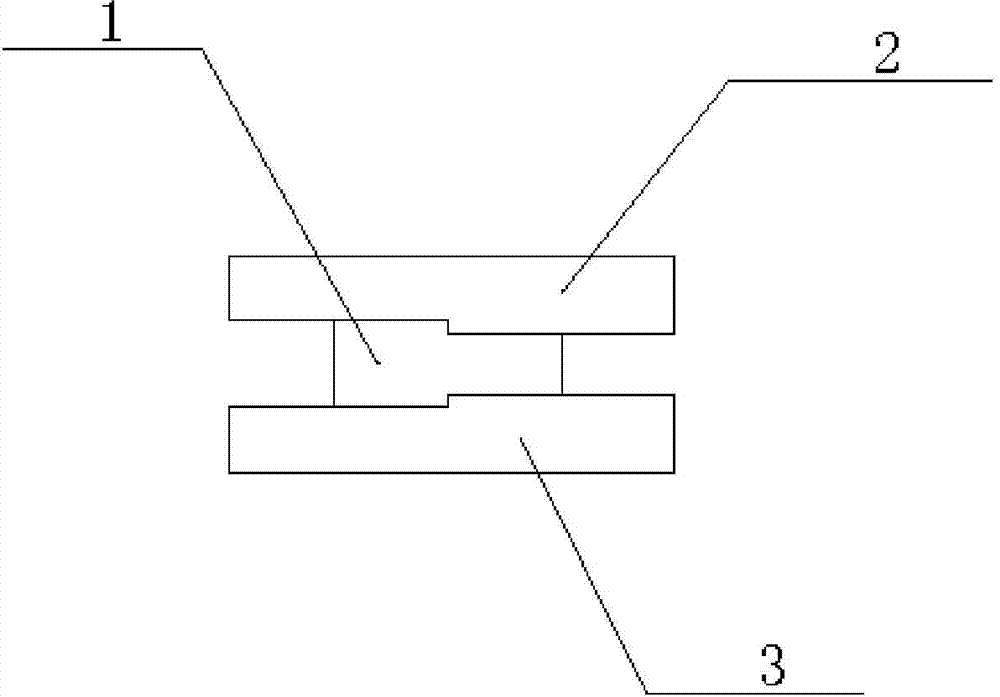
[0022] Specific embodiment 1: This embodiment is a multifunctional tool holder for CNC vertical lathe, including a fixed handle 1, a first L-shaped clamp body 2 and a second L-shaped clamp body 3;

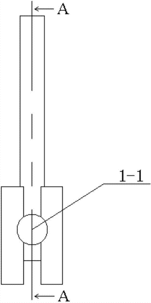
[0023] One end of the fixed handle 1 is provided with two L-shaped grooves; the first L-shaped clip body 2 and the second L-shaped clip body 3 are respectively connected with the two L-shaped grooves at one end of the fixed handle 1; the fixed handle 1 One end, and a through hole 1-1 is provided at the middle position connected with the first L-shaped clip body 2 and the second L-shaped clip body 3;

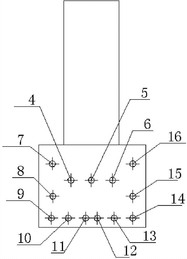
[0024] The outer end surface of the first L-shaped clamp body 2 is processed with a first threaded hole 4, a second threaded hole 5, a third threaded hole 6, a fourth threaded hole 7, a fifth threaded hole 8, and a sixth threaded hole. Hole 9, the seventh screw hole 10, the eighth screw hole 11, the ninth screw hole 12, the tenth screw hole 13, the eleventh screw hole 14, the twelfth ...

specific Embodiment approach 2

[0040] Specific embodiment two: the difference between this embodiment and specific embodiment one is: one end of the fixed handle 1 is provided with two L-shaped grooves, and a depth between the first L-shaped clip body 2 and one end of the fixed handle 1 is The L-shaped groove of 45 mm is connected; the second L-shaped clip body 3 is connected with another L-shaped groove with a depth of 55 mm at one end of the fixed handle 1 . Other steps are the same as in the first embodiment.

specific Embodiment approach 3

[0041] Embodiment 3: The difference between this embodiment and Embodiment 1 or Embodiment 2 is that the diameter of the through hole 1-1 is 60 mm. Other steps are the same as those in Embodiment 1 or 2.


PUM


Abstract

The invention relates to tool chucks, in particular to a multifunctional tool chuck for a numerical control vertical lathe. The multifunctional tool chuck aims at solving the problems that due to the fact that a main engine portion sleeve of a steam turbine is complex in structure, in the machining process, the tool chuck needs to be continuously replaced, and the multifunctional tool chuck special for the numerical control vertical lathe does not exist. The tool chuck comprises a fixed handle, a first L-shaped chuck body and a second L-shaped chuck body. Two L-shaped grooves are formed in one end of the fixed handle. The first L-shaped chuck body and the second L-shaped chuck body are connected with the two L-shaped grooves in the one end of the fixed handle respectively. A through hole is formed in the middle position, connected with the first L-shaped chuck body and the second L-shaped chuck body, of one end of the fixed handle. Double-direction clamping of a lathe tool is achieved. The tool chuck can clamp tools of different sizes and can clamp a lathe tool rod, and therefore the machining range is widened. The multifunctional tool chuck saves cost, and improves the production efficiency.

Description

technical field [0001] The invention relates to a tool holder. Background technique [0002] Usually, the structure of the main engine part of the steam turbine is complex, including the inner cavity of the valve body and the opening groove of the diaphragm cover. Deep and curved surface profile, due to the limitation of the machining range of the turning tool, it is necessary to process the cavity surface in sections, some profile segments require radial or horizontal clamping of the turning tool, and some profile segments require axial or longitudinal clamping of the turning tool , and some deep cavities need to be processed by adding a turning tool bar. For example, the inner hole of the partition sleeve needs to use a turning tool with a small cutter body to process the steam seal groove, and the machining of the partition groove requires a turning tool with a large cutter body. In the past, it was necessary to replace different tool holders, so a multi-functional tool ...

Claims


Application Information

Patent Timeline
Patent Type & Authority Applications(China)
IPC IPC(8): B23B29/08
CPCB23B29/08
Inventor 车延超高伟王文丹栾晓忠高岩李久雷王其江郁洪光张德宇
Owner HARBIN TURBINE
Learn More