Zero-charge starting and stopping circuit of inverter

A technology of stop circuit and inverter control circuit, applied in the direction of electrical components, output power conversion devices, etc., can solve the problems of inverter bridge arm interference conduction, electrical arcing, risky competition of the main circuit, etc., to eliminate device out of control , Eliminate electrical arcing and avoid associated damage

Active Publication Date: 2013-10-23
天津瑞拓电子科技开发有限公司
View PDF5 Cites 7 Cited by
  • Summary
  • Abstract
  • Description
  • Claims
  • Application Information

AI Technical Summary

Problems solved by technology

[0003] However, the establishment and evacuation of the high-voltage bus puts forward new requirements for the inverter control. People pay too much attention to the inverter function, efficiency, volume and weight, etc., but rarely pay attention to the boundary process and static safety characteristics of the inverter start and stop.
At present, due to the lack of strict power-on and power-off control sequences in the field of inverters, there are hidden dangers in starting, stopping, and static
The main problems are as follows: First, there is a risky competition between the power-on of the main circuit and the control circuit during the startup process
Second, there is electrical arcing during the shutdown process, and the failure of high-voltage residual charge control
Third, when the inverter is static, the high-voltage residual charge retained inside is difficult to discharge in a short time, which brings safety hazards to the operation of the machine
From this we can see that the start-stop operation of the inverter is realized by breaking the input air switch. During the high-voltage residual charge discharge process after power-off, the inverter device is in an uncontrolled state, and the inverter bridge arm is easily damaged. Interference conduction phenomenon occurs

Method used


Image

  • Zero-charge starting and stopping circuit of inverter
  • Zero-charge starting and stopping circuit of inverter
  • Zero-charge starting and stopping circuit of inverter

Examples


Embodiment Construction

[0033] Embodiments of the present invention are described in further detail below in conjunction with the accompanying drawings,

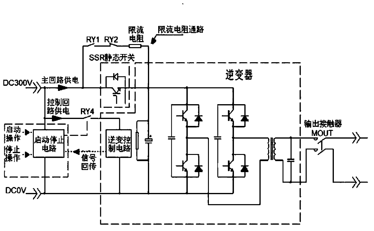
[0034] An inverter zero-charge start and stop circuit, such as image 3 As shown, including the current limiting resistance of the inverter, the DC bus capacitor, and the inverter control circuit, the innovation of the present invention is that it divides the power supply of the inverter into two parts, the main loop power supply and the control loop power supply. Loop power supply is to connect a circuit connected in series with relays RY1 and RY2 on the node between the positive terminal of the power supply and the current limiting resistor, and connect an SSR static switch to the node between the positive terminal of the power supply and the current limiting resistor and the DC bus capacitor to realize the main circuit Power supply control, the power supply of the control loop is to connect the start-stop circuit between the positive and negativ...


PUM


Abstract

The invention relates to a zero-charge starting and stopping circuit of an inverter. The power supply of the inverter is divided into a main loop power supply and a control loop power supply, the main loop power supply is realized by connecting a circuit consisting of a relay RY1 and a relay RY2 in serial connection between a power supply and a current-limiting resistor, an SSR (Solid State Relay) static switch is arranged between the power supply and the current-limiting resistor and between the power supply and a direct-current bus capacitor respectively, the control loop power supply is realized by connecting a starting-stopping circuit between a positive end and a negative end of the power supply, a relay RY4 is arranged between the positive end of the power supply and an inversion control circuit in serial connection, the starting-stopping circuit is externally connected with a starting key and a stopping key, the inversion control circuit is controlled through the relay RY4, the starting-stopping circuit receives a state returning signal of the inversion control circuit, the malfunction time sequence control is realized, and the output end of the inverter is connected with an output contactor MOUT to realize the output control of the inverter. The zero-charge starting and stopping circuit of the inverter has the characteristics that the inversion control is prior to the electrification of a main loop, the main loop is powered off after the inversion control, and the inversion control circuit is not powered down.

Description

technical field [0001] The invention belongs to the field of inverter safety operation control, in particular to an inverter zero-charge start and stop circuit. Background technique [0002] The high-voltage bus inverter technology has the characteristics of low loss and high efficiency. Therefore, most inverters currently adopt a high-voltage DC bus inverter structure. Among them, DC300V-DC800V inverter technology is the most common, which is due to the wide selection of power electronic devices in this range. [0003] However, the establishment and evacuation of the high-voltage bus puts forward new requirements for the inverter control. People pay too much attention to the inverter function, efficiency, volume and weight, etc., but rarely pay attention to the boundary process and static safety characteristics of the inverter start and stop. . At present, due to the lack of strict power-on and power-off control sequences in the field of inverters, there are hidden danger...

Claims


Application Information

Patent Timeline
Patent Type & Authority Applications(China)
IPC IPC(8): H02M1/36
Inventor 黄志忠张航
Owner 天津瑞拓电子科技开发有限公司
Why Eureka
Try Eureka