Scroll expander

一种涡旋膨胀机、涡旋的技术,应用在旋转活塞式机械、旋转活塞式发动机、旋转或摆动活塞发动机等方向,能够解决压力损失、重量增加、大驱动力等问题,达到定位容易、密封性良好的效果

Inactive Publication Date: 2013-10-30
ANEST IWATA CORP
View PDF6 Cites 12 Cited by
  • Summary
  • Abstract
  • Description
  • Claims
  • Application Information

AI Technical Summary

Problems solved by technology

Therefore, there is a problem that it is difficult to align the axes of the two divided drive shafts.
In addition, when used as a scroll expander, because the high-pressure fluid inlet hole provided on one of the divided drive shafts first supplies high-pressure working medium to one expansion chamber, and then passes through the partition wall of the expansion chamber. The structure that supplies the working medium to the other expansion chamber through the hole provided in the upper part has the problem that pressure loss occurs when the working medium passes through the hole, and the working medium cannot be equally supplied to both expansion chambers.
In addition, since the driven scroll has a casing that covers the expansion chamber forming portion, the weight increases, and a large driving force is required to rotate the driven scroll.

Method used


Image

  • Scroll expander
  • Scroll expander
  • Scroll expander

Examples


Embodiment approach 1

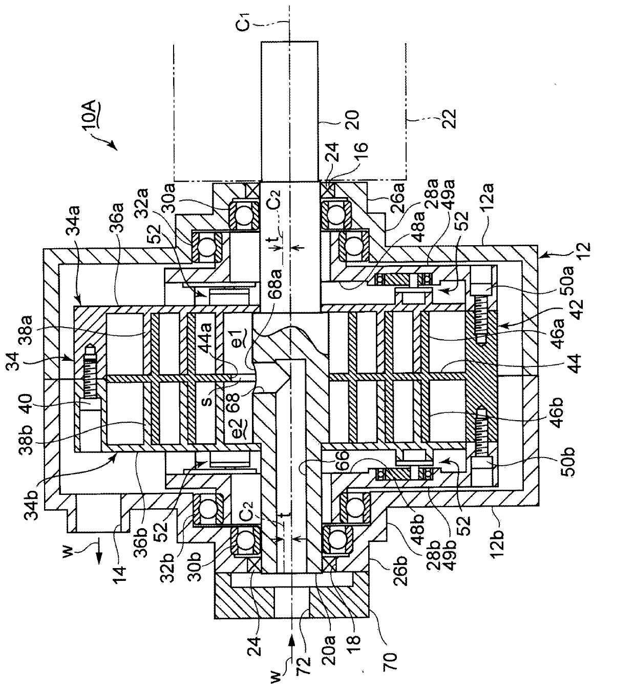
[0030] according to figure 1 and figure 2 A first embodiment of the device of the present invention will be described. The scroll expander of this embodiment can be applied to, for example, the above-mentioned dual-fuel power generation system. In this power generation system, a pressurized working medium with a low boiling point is introduced into a scroll expander, the drive shaft of the scroll expander is rotated by the expansion force of the working fluid, and power is generated by a generator connected to the drive shaft. exist figure 1 Among them, the casing 12 of the scroll expander 10A includes a pair of hollow cylindrical housings 12a and 12b. The ends of the casings 12a and 12b are butted against each other, and a hollow space is formed inside. A discharge port 14 for discharging the expanded working medium w to the outside of the casing 12 is provided on the outer peripheral portion of the end surface of the housing 12b.

[0031] Openings 16 and 18 are formed ...

Embodiment approach 2

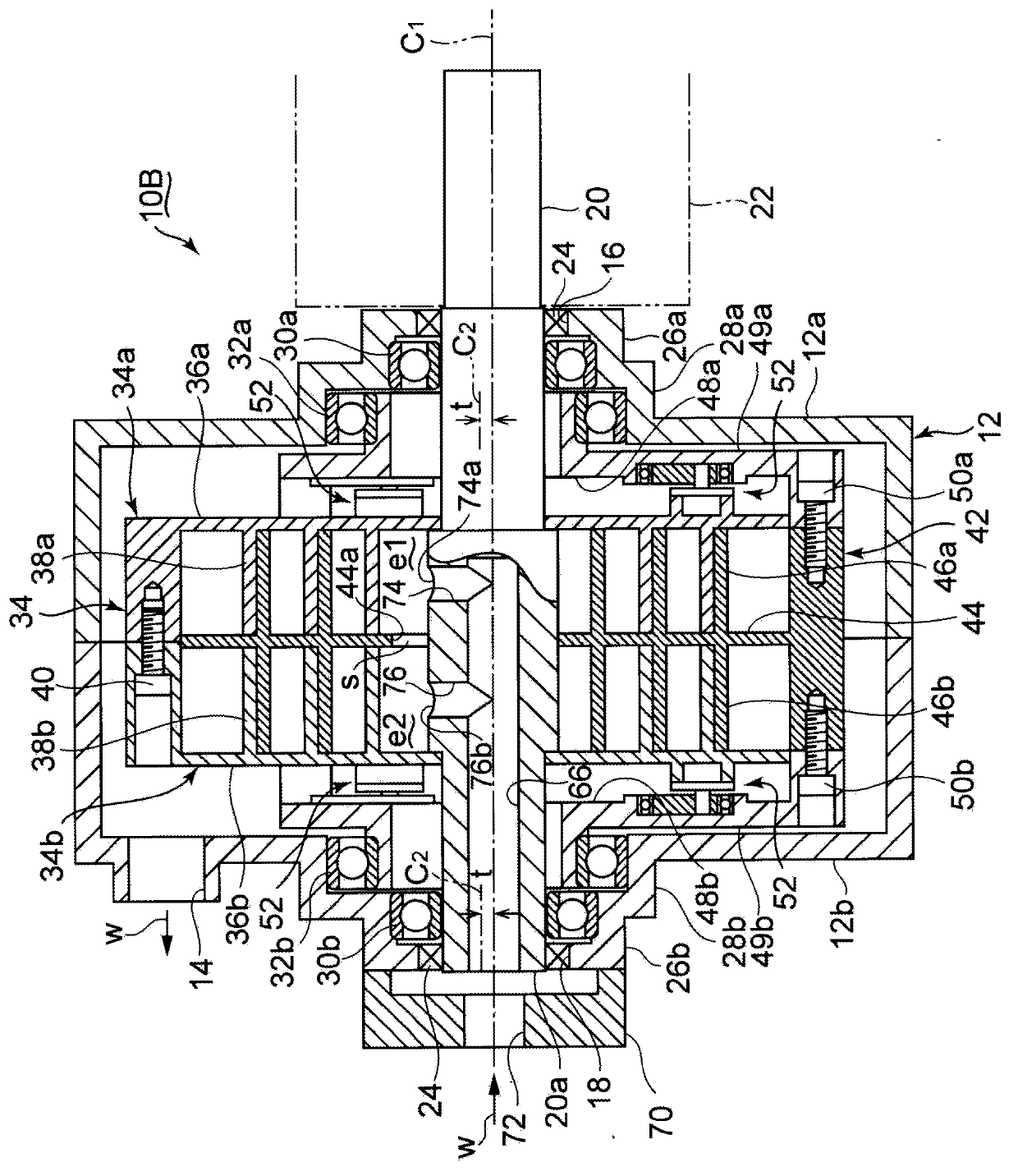
[0043] Next, according to image 3 A second embodiment of the device of the present invention will be described. In the scroll expander 10B of the present embodiment, two radial holes 74 and 76 respectively opening to the expansion chambers e1 and e2 are connected to the working medium introduction hole 66 . The opening 74a of the radial hole 74 opens toward the axial center of the expansion chamber e1, and the opening 76a of the radial hole 76 opens toward the axial center of the expansion chamber e2. The opening area of ​​the opening 74a is the same as that of the opening 76a. Other structures are the same as those of the first embodiment.

[0044] According to the present embodiment, the supply amount of the working medium w supplied from the radial holes 74 to the expansion chamber e1 and the supply amount of the working medium w supplied from the radial holes 76 to the expansion chamber e2 can be made uniform. In addition, there is no need to arrange the opening 68 tow...


PUM


Abstract

The invention provides a double rotation type scroll expander with double expansion chamber. One object of the present invention is to provide a double rotation type scroll expander having double expansion chambers in which axial center alignment of a drive shaft is not required, a working medium supply passage in which working medium leakage and pre-expansion due to a temperature reduction do not occur can be formed, and the working medium can be supplied evenly to the double expansion chambers. A single integrated drive shaft (20) is disposed to penetrate the interior of a housing (12), the double expansion chambers (e1, e2) are formed by a drive scroll body (34) and a driven scroll body (42), and a working medium introduction hole (66) is provided in an axial direction of the drive shaft such that the working medium (w) is supplied evenly to the double expansion chambers through the working medium introduction hole via a radial direction hole (68). The drive shaft and the drive scroll body formed integrally with the drive shaft rotate while the driven scroll body (42) rotates synchronously with the drive scroll shaft (34) via an interlocking mechanism (52).

Description

technical field [0001] The present invention relates to a double-rotation type scroll expander in which a driving scroll body and a driven scroll body rotate synchronously. Background technique [0002] Existing power generation systems are mainly large-scale equipment with hundreds of kW or more, and small-scale power generation systems are dominated by engine-driven generators with simple structures. Recently, however, the need for and market for small-scale power generation has increased due to increased desire for energy conservation and the establishment of the Special Measures Act for Renewable Energy. On the one hand, solar or wind power has not yet improved the price-performance ratio. On the other hand, a dual-fuel power generation system has been developed that uses hot water or steam at 75°C to 150°C as a heat source, and drives a small generator through a working medium with a low boiling point. [0003] Among such countermeasures, the scroll expander has a str...

Claims


Application Information

Patent Timeline
Patent Type & Authority Applications(China)
IPC IPC(8): F01C1/02
CPCF04C29/0078F01C1/0238F01C21/18F04C2240/603F04C18/00
Inventor 宇波厚藤冈完
Owner ANEST IWATA CORP
Why Eureka
Try Eureka