Unlock instant, AI-driven research and patent intelligence for your innovation.

Steering system with overload protection

A technology of steering system and steering rack, which is applied in the field of steering system of motor vehicles, and can solve the problems of preventing measures for destroying the steering system, not providing them, etc.

Active Publication Date: 2013-11-20
THYSSENKRUPP PRESTA AG
View PDF9 Cites 1 Cited by
  • Summary
  • Abstract
  • Description
  • Claims
  • Application Information

AI Technical Summary

Problems solved by technology

But no precautions are provided to avoid damage to the steering system

Method used


Image

  • Steering system with overload protection
  • Steering system with overload protection
  • Steering system with overload protection

Examples


Embodiment Construction

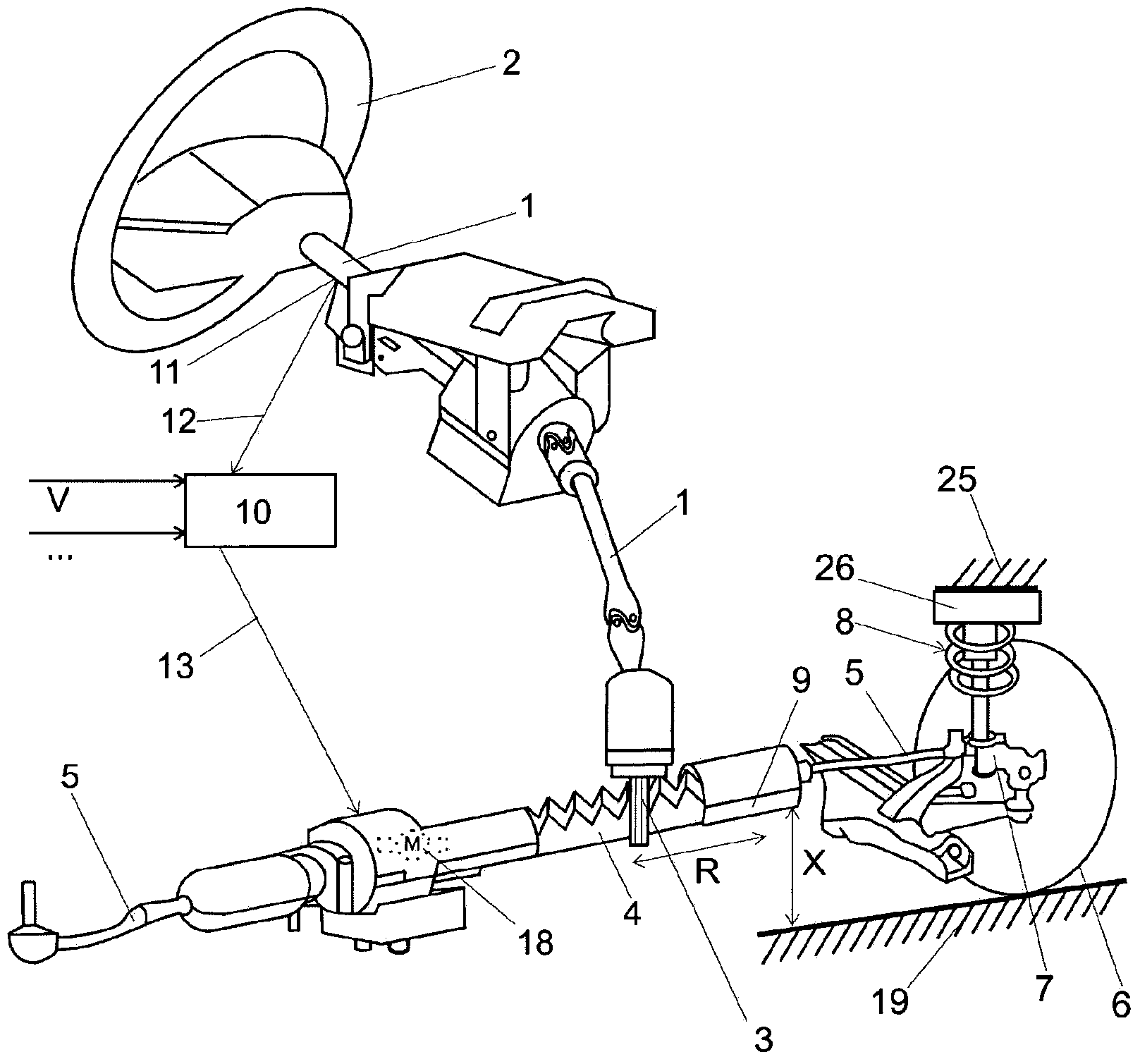
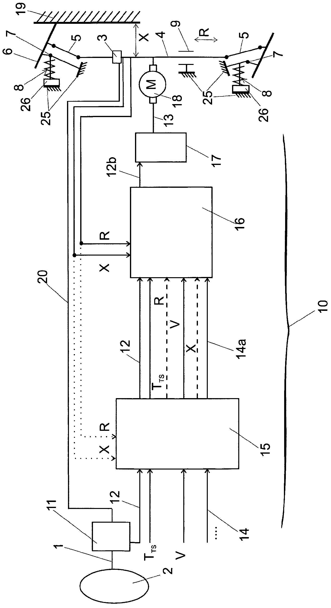
[0022] figure 1 A steering system for a motor vehicle is shown in the form of a diagram with a steering shaft 1 holding a steering wheel 2 at its upper end and a steering pinion 3 at its lower end. The steering pinion 3 meshes with teeth on the rack 4 so that when the steering wheel 2 is turned, the rack 4 is displaced in its axial direction. The rack is guided in the rack box 9 which is fixed to the vehicle structure 25 corresponding to the vehicle chassis. The tie rods 5 are attached to both ends of the rack 4 and are connected to the steering knuckle 7 which in turn supports the steering wheels 6. Therefore, the rotation of the steering wheel 2 causes the steering wheel 6 to pivot in a known manner. The steering wheel 6 contacts the road surface 19. A MacPherson-type strut unit 8 or a similar biasing and damping unit fixed to the vehicle structure 25 corresponding to the vehicle chassis allows the linear movement of the steering wheel 6 to improve the comfort of the driver...


PUM


Abstract

A method for operating an electromechanical steering system for a motor vehicle with variable chassis height, with a steering rack (4), which is driven by a servo motor (18) through a re-circulating ball screw drive, with a control unit (10), which receives input signals and generates output signals for driving the servo motor (18), the output signals being representative of an assist torque (T) to be provided by the steering system, is characterised in that in operation the control unit (10) is, receiving or generating a chassis height signal (X) indicative of the current chassis height of the vehicle, and limiting the assist torque (T) on the basis of the chassis height signal (X) to an upper limit, wherein the upper limit is decreased with an increase of the difference between the current chassis height and a mean chassis height.

Description

Technical field [0001] The invention relates to a method for operating an electromechanical steering system for a motor vehicle having the features of the preamble of claim 1 and a steering system for a motor vehicle having the features of the preamble of claim 9. Background technique [0002] The known design form of the electric power steering system is that the steering assist is directly applied to the rack by means of recirculating ball screw transmission, wherein the rack is provided with a corresponding roller screw. As far as rack-and-pinion steering systems are concerned, a generally known principle is to provide a connection between the rack and the steering wheel through a track rod attached to the free end of the rack. Tie rods are sometimes called tie rods. The tie rod and the rack are not coaxially aligned, but at a certain angle relative to the axis of the rack. Therefore, the force acting on the rack from the steering wheel via the tie rod has an axial component...

Claims


Application Information

Patent Timeline
IPC IPC(8): B62D5/04B62D6/00
CPCB62D6/06B62D5/0463
Inventor 多拉·绍博尔奇伊姆雷·拜纽马顿·库什利奇山多尔·胥奇
Owner THYSSENKRUPP PRESTA AG