
Apparatus for Ladle Working Lining Construction

A technology of working lining and ladle, applied in the direction of manufacturing tools, metal processing equipment, casting molten material containers, etc., can solve the problems of high labor intensity, unsuitable for masonry, and inability to masonry the bottom of the ladle.

Active Publication Date: 2015-10-21
CHINA FIRST HEAVY IND
View PDF7 Cites 2 Cited by
  • Summary
  • Abstract
  • Description
  • Claims
  • Application Information

AI Technical Summary

Problems solved by technology

[0002] The working lining of the ladle is made of refractory bricks, which are generally built by hand, which has the defects of high labor intensity and low building efficiency, and it is difficult to guarantee the precision of the building, which makes the service life of the working lining of the ladle low.
In the existing ladle automatic masonry equipment, the masonry platform can be raised along the vertical support fixed at the bottom of the ladle, the bricklaying arm is fixed on the masonry platform, and the end of the bricklaying arm is suspended by a rope tongs to take bricks , laying bricks, but the method of hanging bricks by ropes cannot guarantee the accuracy of masonry, and the whole device is fixed on the bottom of the bag, making it impossible to lay the bottom of the bag
Another type of equipment used for converter masonry. The main body of the masonry is gradually raised from the opening below the converter, and then it is built layer by layer by manipulators. However, there is no opening at the bottom of the ladle, so it is not suitable for the masonry of the working lining of the ladle.

Method used


Image

  • Apparatus for Ladle Working Lining Construction
  • Apparatus for Ladle Working Lining Construction
  • Apparatus for Ladle Working Lining Construction

Examples


Embodiment Construction

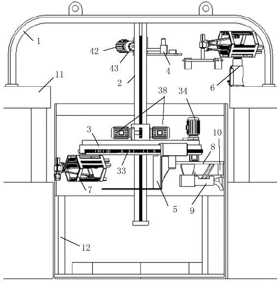
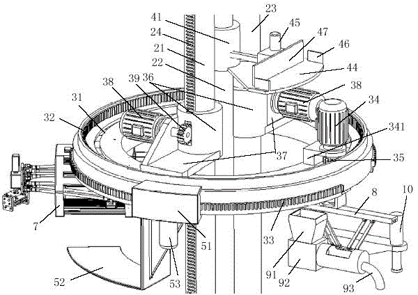
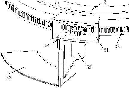
[0017] Such as figure 1 As shown, the device for ladle lining masonry of the present invention includes a support frame 1, a telescopic column group 2, a rotary lifting platform 3, a brick lifting plate 4, a brick rotary plate 5, a bricklaying manipulator 7, and a pouring posture adjustment mechanism 8 , screw conveyor 9, vibrating hammer 10 and feeding manipulator 6, the bottom surface of the support frame 1 is erected on the ladle foundation 11 and is located above the ladle 12, and the top of the telescopic column group 2 is vertically arranged at the center of the top surface of the support frame 1 And extend into the ladle 12, the rotary lifting platform 3 and the brick lifting plate 4 are set on the telescopic column group 2 and lift along the telescopic column group 2, the brick rotary plate 5 is set on the rotary lifting platform 3 The outer edge is rotated along the rotary lifting platform 3. The bricklaying manipulator 7 and the pouring attitude adjustment mechanism ...


PUM


Abstract

The invention discloses a device for building a steel ladle working lining. The bottom face of a supporting framework of the device is arranged on a steel ladle foundation in an erected mode and located above a steel ladle, the top end of a telescopic stand column set is vertically arranged in the center of the top face of the supporting framework and extends into the steel ladle, a rotation lifting platform and a brick lifting disc are arranged on the telescopic stand column set and lift along the telescopic stand column set, the brick lifting disc is arranged at the outer edge of the rotation lifting platform and rotates along the rotation lifting platform, a brick building mechanical arm and a pouring posture adjusting mechanism are fixedly arranged at the outer edge of the rotation lifting platform in a spaced mode, the tail end of the pouring posture adjusting mechanism moves horizontally within a vertical surface in a two-dimensional mode, a spiral conveyer and a vibratory hammer are fixedly arranged at the tail end of the pouring posture adjusting mechanism, and a feeding mechanical arm is arranged on the steel ladle foundation and is close to the steel ladle. The device brings convenience to automatic building of the steel ladle working lining, effectively relieves labor intensity of the building operation, improves building efficiency, ensures building accuracy of the steel ladle working lining, and prolongs the service life of the steel ladle working lining.

Description

technical field [0001] The invention relates to a device for ladle working lining construction. Background technique [0002] The working lining of the ladle is made of refractory bricks, which are usually built manually, which has the defects of high labor intensity and low building efficiency, and it is difficult to guarantee the precision of the masonry, which makes the service life of the working lining of the ladle low. In the existing ladle automatic masonry equipment, the masonry platform can be raised along the vertical support fixed at the bottom of the ladle, the bricklaying arm is fixed on the masonry platform, and the end of the bricklaying arm is suspended by a rope tongs to take bricks , put bricks, but the method of placing bricks by rope hanging cannot guarantee the accuracy of masonry, and the whole device is fixed on the bottom of the bag, so that the bottom of the bag cannot be built by masonry. Another type of equipment used for converter masonry, the ma...

Claims


Application Information

Patent Timeline
Patent Type & Authority Patents(China)
IPC IPC(8): B22D41/02
Inventor 高峰何俊金振林吴生富马克
Owner CHINA FIRST HEAVY IND
Learn More