Electromagnetic Docking System

An electromagnetic and docking rod technology, which is applied in the direction of aerospace vehicle docking devices, etc., can solve the problems of low feasibility and high requirements for space electromagnetic docking control, and achieve the effect of not consuming working fluid

Active Publication Date: 2016-04-20
NAT UNIV OF DEFENSE TECH
View PDF3 Cites 0 Cited by
  • Summary
  • Abstract
  • Description
  • Claims
  • Application Information

AI Technical Summary

Problems solved by technology

[0006] The purpose of the present invention is to provide an electromagnetic docking system to solve the existing technical problems of space electromagnetic docking control requirements and low feasibility

Method used


Image

  • Electromagnetic Docking System
  • Electromagnetic Docking System
  • Electromagnetic Docking System

Examples


Embodiment Construction

[0035] The embodiments of the present invention will be described in detail below with reference to the accompanying drawings, but the present invention can be implemented in many different ways defined and covered by the claims.

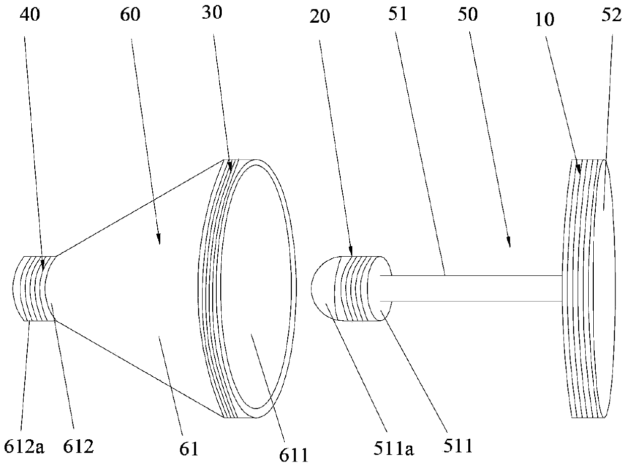
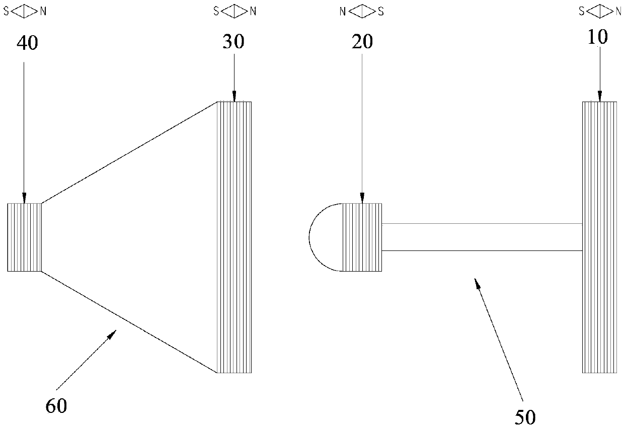
[0036] refer to figure 1 and figure 2 , a preferred embodiment of the present invention provides an electromagnetic docking system, including an active system 50 and a passive system 60 . Wherein, the first electromagnetic coil 10 and the second electromagnetic coil 20 are arranged in parallel on the active system 50 ; the third electromagnetic coil 30 and the fourth electromagnetic coil 40 are arranged in parallel on the passive system 60 . The first electromagnetic coil 10 is axially far away from the passive system 60 relative to the second electromagnetic coil 20 , and the third electromagnetic coil 30 is axially close to the active system 50 relative to the fourth electromagnetic coil 40 . The current direction of the first electromagnetic c...


PUM


Abstract

The invention discloses an electromagnetic butt joint system. The electromagnetic butt joint system comprises a driving system and a driven system, wherein a first electromagnetic coil and a second electromagnetic coil are arranged on the driving system in parallel and in a spaced mode, and a third electromagnetic coil and a fourth electromagnetic coil are arranged on the driven system in parallel and in a spaced mode. Attractive force is generated in the butt joint process of the first electromagnetic coil and the third electromagnetic coil, and repulsive force is generated in the butt joint process of the second electromagnetic coil and the fourth electromagnetic coil. Due to the fact that the driving system and the driven system are respectively provided with each large electromagnetic coil and each small electromagnetic coil, in the butt joint process, the driving system gets close to the driven system at the system initial velocity under the action of the attractive force between the two large electromagnetic coils, and in the getting-close process, the butt joint velocity of the driving system and the driven system slows down under the action of repulsive force of the two small electromagnetic coils till the driving system and the driven system reach the balanced stationary state. Automatic and flexible butt joint of the driving system and the driven system is achieved without a control system.

Description

technical field [0001] The present invention relates to the technical field of space rendezvous and docking, in particular to an electromagnetic docking system for space rendezvous and docking. Background technique [0002] Space rendezvous and docking technology is the basis for implementing difficult space tasks such as on-orbit refueling, on-orbit maintenance, space rescue, and space assembly, and it is also one of the means of space confrontation. Therefore, the development of autonomous rendezvous and docking technology will make space technology more widely used. [0003] At present, the commonly used space rendezvous and docking technology is mainly based on thrusters. There are some problems that need to be solved urgently, such as: avoiding or reducing the uncertainty generated in the collision process; eliminating the plume pollution and impact load brought by the thruster; energy consumption, etc. The above problems can be effectively avoided by using flexible e...

Claims


Application Information

Patent Timeline
Patent Type & Authority Patents(China)
IPC IPC(8): B64G1/64
Inventor 黄奕勇张强陈小前赵勇姚雯陈勇张翔韩伟
Owner NAT UNIV OF DEFENSE TECH
Why Eureka
Try Eureka