Step door pocket capable of cut and free of upper and lower grooves

A technology of steps and door pockets, applied in the direction of window/door frames, etc., can solve problems such as waste of electricity, damage in transportation, and labor cost, and achieve the effects of saving machine costs, increasing production, and reducing dust

Active Publication Date: 2013-11-27
重庆正格技术创新服务有限公司
View PDF5 Cites 1 Cited by
  • Summary
  • Abstract
  • Description
  • Claims
  • Application Information

AI Technical Summary

Problems solved by technology

In particular, the combined custom-made door cover production method requires a slotting machine for slotting, which not only wastes electricity but also generates a lot of dust, which is not environmentally friendly, and requires a variety of links and a lot of labor, which increases the difficulty of management, consumes construction time and production-related series costs
In the process of actual measurement, transportation or export transportation, handling, and installation, there are still a series of problems such as measurement errors, transportation damage, and handling damage. As a result, the door covers that have been painted and fixed are not suitable for on-site installation after leaving the factory. cut to use
In the prior art, there are three types of step door covers, namely: the combined solid step door cover, the combined hollow step door cover and the one-time formed hollow step door cover. The common disadvantage is that the steps and rubber strip grooves need to be specially manufactured. , and cannot be cut to accommodate wall thickness variations and door leaf thickness variations
In the production of traditional door casings, how to form steps and rubber strip grooves for the stepped door casings used for installing doors, and how to not cut the casing boards during installation to adapt to various wall thicknesses and various door leaf thicknesses have always been step-by-step in the industry. The four major industrial technical problems in the production of door covers require a lot of labor to set up steps and strip grooves

Method used


Image

  • Step door pocket capable of cut and free of upper and lower grooves
  • Step door pocket capable of cut and free of upper and lower grooves
  • Step door pocket capable of cut and free of upper and lower grooves

Examples


Embodiment 1

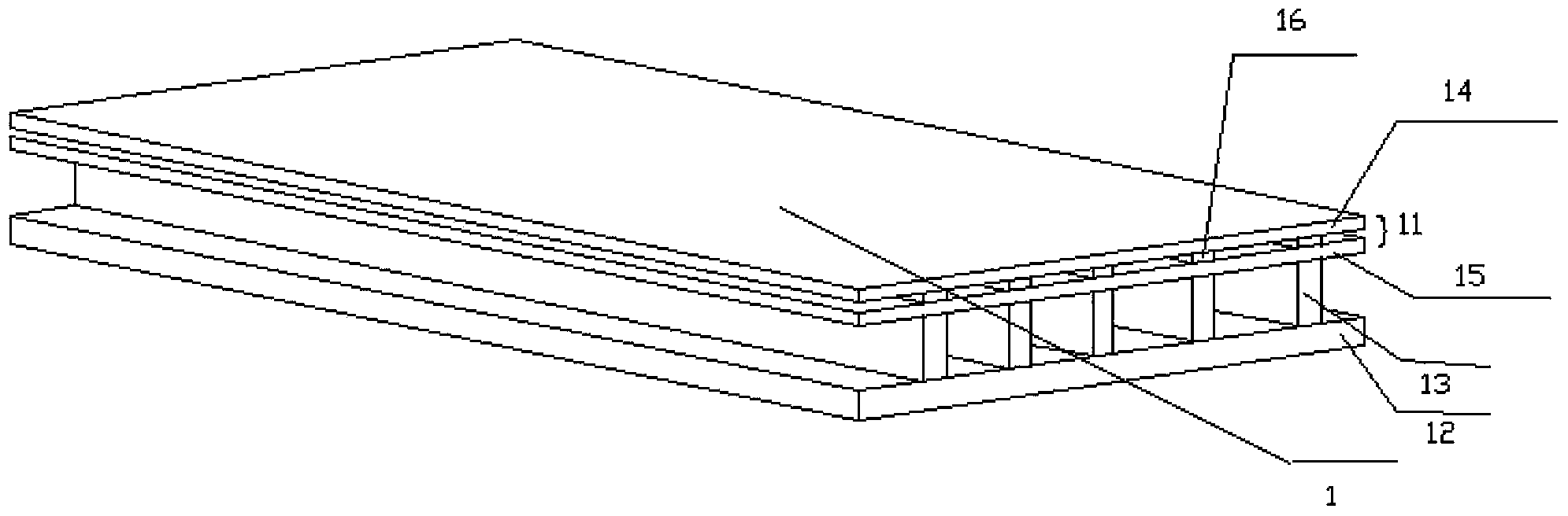
[0045] The first preferred embodiment of the present invention includes: a cover plate 1, a step member, lines and rubber strips.

[0046] The structure of cover plate 1 described in the present embodiment is:

[0047] The cover plate 1 includes a surface layer 11, a bottom layer 12 and several first connecting ribs 13, and the surface layer 11 and the bottom layer 12 are connected through several first connecting ribs 13, thereby forming a Several stepped slots. The surface layer 11 includes an upper layer 14 , a lower layer 15 and a plurality of second connecting ribs 16 , the upper layer 14 and the lower layer 15 are connected through a plurality of second connecting ribs 16 , thereby forming a glue strip slot on the surface layer 11 . The inner surface of the surface layer 11 of the cover plate 1 is parallel to the inner surface of the bottom layer 12 . The door cover structure automatically generates the rubber strip slot and the step slot, and does not need to use a sp...

Embodiment 2

[0067] The second preferred embodiment of the present invention includes cover boards, rubber strips, step components and lines.

[0068] Please refer to Figure 12, the cover plate includes a surface layer 115, a bottom layer 111 and a first connecting rib 116, and the surface layer 115 and the bottom layer 111 are connected by several first connecting ribs 116, thereby forming several Step slots, the surface layer 115 includes an upper layer 110, a lower layer 114 and some second connecting ribs 113, the upper layer 110 and the lower layer 114 are connected by several second connecting ribs 113, thereby forming a glue strip on the surface layer 115 Slot 112. The inner surface of the surface layer 115 of the cover plate 1 is parallel to the inner surface of the bottom layer 111 .

[0069] In this embodiment, the rubber strip slot 112 of the cover board extends along a direction perpendicular to the length direction of the cover board (that is, the rubber strip slot 112 exte...

Embodiment 3

[0072] The step door cover that can be cut without opening the upper and lower grooves in the third preferred embodiment of the present invention is different from the step door cover that can be cut without opening the upper and lower grooves in the first preferred embodiment and the second preferred embodiment only in the cover plate The first connecting rib and the second connecting rib included in the structure are different, and the rest of the structure is the same as that of the first preferred embodiment and the second preferred embodiment of the present invention. Therefore, starting from simplicity, here we will mainly describe the parts that are different from the first embodiment and the second embodiment, that is, focus on explaining the structure of the first connecting rib and the second connecting rib of the step door cover plate that can be cut without opening the upper and lower grooves. .

[0073] The connecting ribs hereinafter all include the first connect...


PUM


Abstract

The invention belongs to the field of door pockets of complete sets of doors and particularly relates to a step door pocket capable of cut and free of upper and lower grooves. The door pocket comprises a pocket board and a step member, wherein the pocket board comprises a surface layer, a bottom layer and a plurality of connecting ribs. The surface layer is connected with the bottom layer through the plurality of connecting ribs so as to form a plurality of invisible or hidden step inserting grooves between the surface layer and the bottom layer, and the surface layer comprises an upper layer, a lower layer and a plurality of second connecting ribs. The upper layer is connected with the lower layer through the plurality of second connecting ribs so as to form a plurality of invisible or hidden rubber inserting grooves in the surface layer, the rubber inserting grooves and the step inserting grooves of the pocket board continuously and repeatedly arranged, the inner surface of the surface layer of the pocket board and the inner surface of the bottom layer are parallel, the surface layer is 6-15mm, and the step member is connected with the pocket board so as to form a step.

Description

technical field [0001] The invention belongs to the field of door pockets for set doors, in particular to a stepped door pocket that can be cut without opening upper and lower grooves. Background technique [0002] The large-scale production of step door pockets has become the development trend of the suit door industry in the future. However, due to the ever-changing thickness and actual size of the walls on site, it is difficult to achieve large-scale production. At present, the production of the door and window industry is based on the actual size of the site to order production, tailor-made door cover. Door casing manufacturers often need many sets of molds of different sizes to produce door casings, or do not need molds to produce combined door casings of different sizes to suit walls of different thicknesses. In particular, the combined custom-made door cover production method requires a slotting machine for slotting, which not only wastes electricity but also generat...

Claims


Application Information

Patent Timeline
Patent Type & Authority Applications(China)
IPC IPC(8): E06B1/34
Inventor 程礼中
Owner 重庆正格技术创新服务有限公司
Why Eureka
Try Eureka