Door and window sleeve capable of cut and closed up

A technology of door and window covers and closing strips, which is applied in the field of door and window covers, can solve the problems of inability to cut and adjust, cannot be re-engaged, and cannot be mass-produced, so as to achieve the effect of saving machine costs and reducing dust

Active Publication Date: 2013-11-27
重庆正格技术创新服务有限公司
View PDF8 Cites 1 Cited by
  • Summary
  • Abstract
  • Description
  • Claims
  • Application Information

AI Technical Summary

Problems solved by technology

[0004] The Chinese invention patent with the application number of 200910140312.1 discloses a door cover. Although it solves the problem that the on-site installation can be fine-tuned, the line slot of the door cover needs to be specially opened by a slotting machine, which increases the production cost.
Moreover, after opening the line slots, it cannot be cut and adjusted according to any wall thickness, so it cannot be mass-produced
After the above two cases were cut, the line slots were cut off and could not be engaged again.
Moreover, the raw materials at the abdication are exposed, so it cannot be mass-produced or sold on-the-spot

Method used


Image

  • Door and window sleeve capable of cut and closed up
  • Door and window sleeve capable of cut and closed up
  • Door and window sleeve capable of cut and closed up

Examples


Embodiment 1

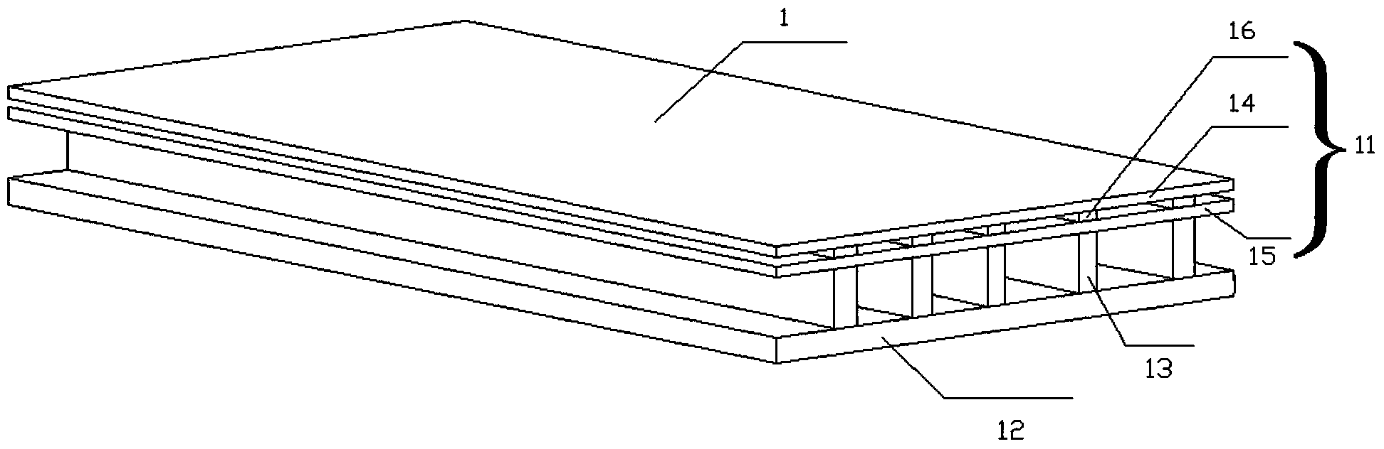
[0064] The first preferred embodiment of the present invention includes: a cover plate 1, a step member and a line.

[0065] The structure of the cover plate 1 in this embodiment is:

[0066] The cover plate 1 includes a surface layer 11, a bottom layer 12 and a number of first connecting ribs 13. The surface layer 11 and the bottom layer 12 are parallel to each other and are connected by a number of first connecting ribs 13 perpendicular to the surface layer 11, thereby Between the surface layer 11 and the bottom layer 12 is formed a line slot that intermittently penetrates the entire cover plate 1. The surface layer 11 includes an upper layer 14, a lower layer 15 and a number of second connecting ribs 16. In this embodiment, the upper layer 14 and the lower layer 15 are parallel to each other, and the upper layer 14 and the lower layer 15 are connected by a plurality of second connecting ribs 16 perpendicular to the upper layer 14, thereby forming a discontinuity on the surface ...

Embodiment 2

[0092] The door and window cover of the second preferred embodiment of the present invention differs from the first preferred embodiment only in the way of connecting the lines and the cover plate 1. The first embodiment adopts the retreat installation method, and the present embodiment adopts the full cover installation method. The rest of the structure is the same as the door and window cover of the first preferred embodiment of the present invention. Therefore, for the sake of simplicity, the different parts from the first embodiment are mainly described here, that is, the connection method of the line and the cover plate 1 is emphasized.

[0093] The door and window cover of the second preferred embodiment of the present invention includes: a cover plate 1, a line and a step member.

[0094] The connection method of the cover plate 1 and the step member is the same as that of the first embodiment.

[0095] Please refer to Figure 14 A preferred implementation of the line in this...

Embodiment 3

[0101] The difference between the door and window cover of the third preferred embodiment of the present invention and the door and window cover of the first and second preferred embodiments lies in the way in which the steps are formed. The rest of the structure is the same as the first preferred embodiment of the present invention. The door and window cover of the second preferred embodiment is the same. Therefore, for the sake of brevity, the differences from the first embodiment and the second preferred embodiment are mainly described here, that is, the step formation structure is emphasized.

[0102] Please refer to Figure 5 , The door and window cover of the third preferred embodiment of the present invention includes: a cover plate, a line and a closing strip.

[0103] The inner surface of the surface layer of the cover plate is parallel to the inner surface of the bottom layer, and the surface layer and the bottom layer are connected by a plurality of first connecting ribs...


PUM


Abstract

The invention belongs to the field of door and window sleeves, in particular to a door and window sleeve capable of cut and closed up. The door and window sleeve comprises a sleeve board and lines, wherein the sleeve board comprises a surface layer, a bottom layer and a plurality of connecting ribs. The surface layer is connected with the bottom layer through the plurality of connecting ribs so as to form a plurality of hidden or invisible line inserting grooves between the surface layer and the bottom layer, and the surface layer comprises an upper layer, a lower layer and a plurality of second connecting ribs. The upper layer is connected with the lower layer through the plurality of second connecting ribs so as to form a plurality of hidden or invisible closing-up line inserting grooves between the upper layer and the lower layer. The line inserting grooves and the closing-up line inserting grooves are continuously and repeatedly arranged, and the lines are connected with the line inserting grooves on the outmost side. The door and window sleeve can be cut according to the actual requirements, so that a production factory can achieve installation of the door and window sleeves with different wall thicknesses only by needing a set of moulds.

Description

Technical field [0001] The invention belongs to the processing field of door sleeves and door and window sleeves of a set door, in particular to a cutable and retractable door and window sleeve. Background technique [0002] At present, the door and window cover is developing in the direction of spot, large-scale, cut and no waste. However, most doors and windows use abdicated door and window cover. This kind of spot abdicated door and window cover has the following four major technical problems in the industry: 1. After the door and window cover is cut, the upper abducted position is exposed, and the slot at the lower line is cut off. Finished snapping, so it can not adapt to the installation of various wall thickness sizes. Third, it is more difficult that the door and window cover cannot be universally converted to the Anmen step door cover. Fourth, a line slot must be opened at the step. The above is the door and window cover The four major technical problems in the industry...

Claims


Application Information

Patent Timeline
Patent Type & Authority Applications(China)
IPC IPC(8): E06B1/34
CPCE06B3/4654
Inventor 程礼中
Owner 重庆正格技术创新服务有限公司
Why Eureka
Try Eureka