Waterpower oscillator

A technology of hydraulic oscillator and vibration valve, which is applied in vibration drilling and other directions, can solve the problems of restricting drill pressure, large positive pressure, and increased drilling tool friction, so as to absorb drill string vibration and drill bit impact force, and relieve lateral pressure. and longitudinal vibration, reducing the effect of back pressure phenomenon

Inactive Publication Date: 2013-11-27
YANGZHOU TIANYE GASOLINEEUM MACHINERY
View PDF6 Cites 20 Cited by
  • Summary
  • Abstract
  • Description
  • Claims
  • Application Information

AI Technical Summary

Problems solved by technology

[0003] 1. Due to the large well deviation, the weight of the drill string in the wellbore direction is small or nearly zero, so it is difficult to meet the pre-designed WOB;
[0004] 2. In horizontal wells, due to the large positive pressure of the drill string on the well wall due to its own weight, the friction of the drilling tool on the well wall is increased, thereby restricting the effective drilling pressure applied to the drill bit;
[0005] 3. For horizontal wells, since the horizontal section of construction is getting longer and longer, however, during the construction process of the well section with large well deviation, underpressure and sticking often occur;
[0006] 4. For compound drilling, especially in the sliding drilling process of downhole power tools, it is impossible to ensure that the real and effective WOB is applied to the drill bit, which seriously affects the average ROP and drilling cycle of the whole well.

Method used


Image

  • Waterpower oscillator
  • Waterpower oscillator
  • Waterpower oscillator

Examples


Embodiment Construction

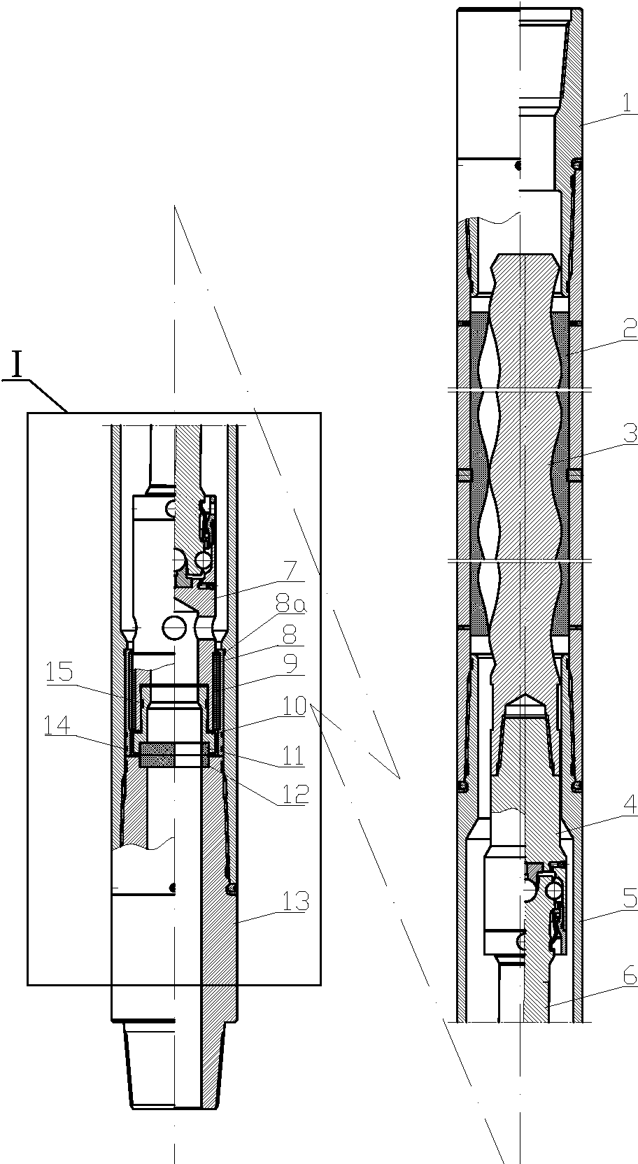
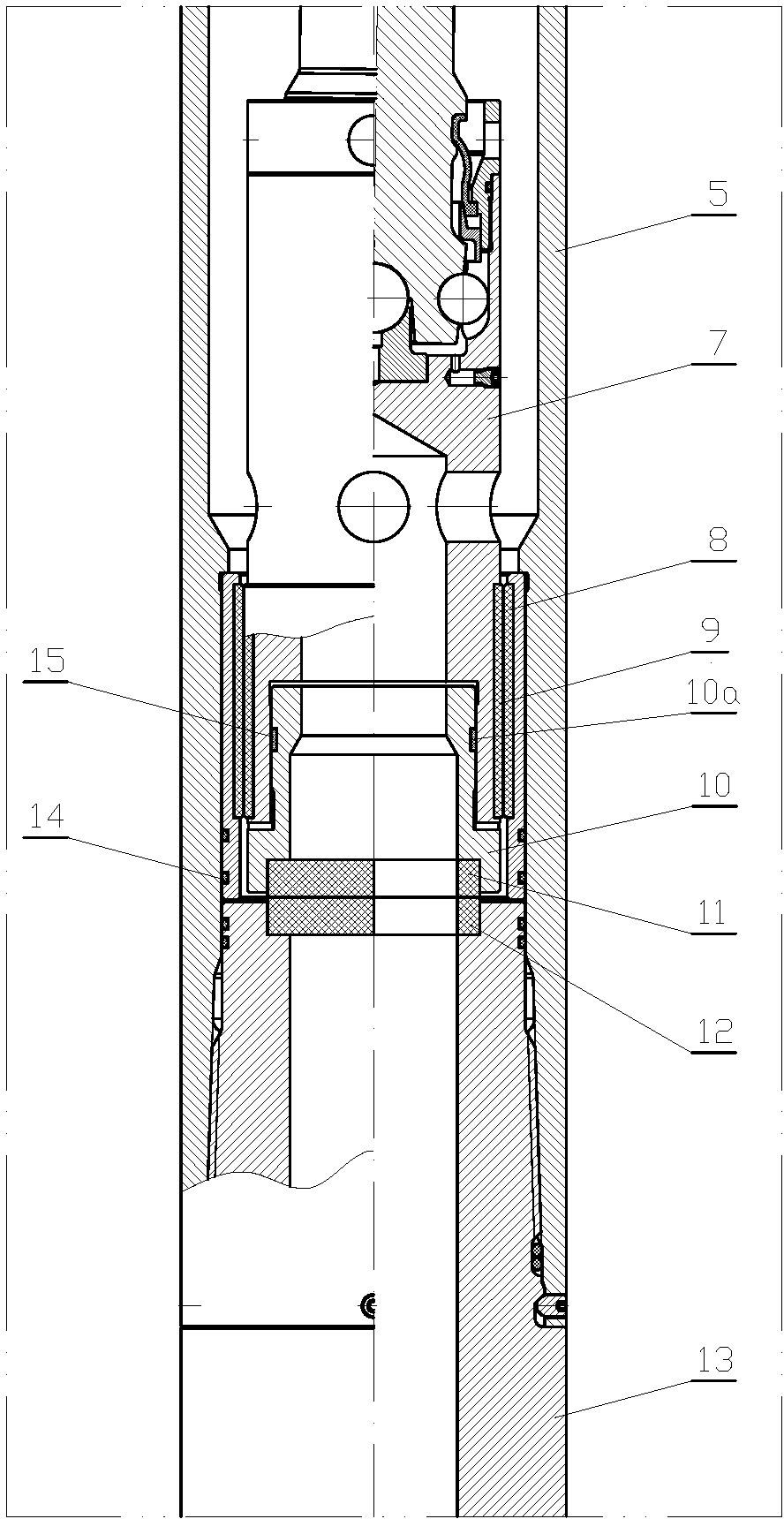
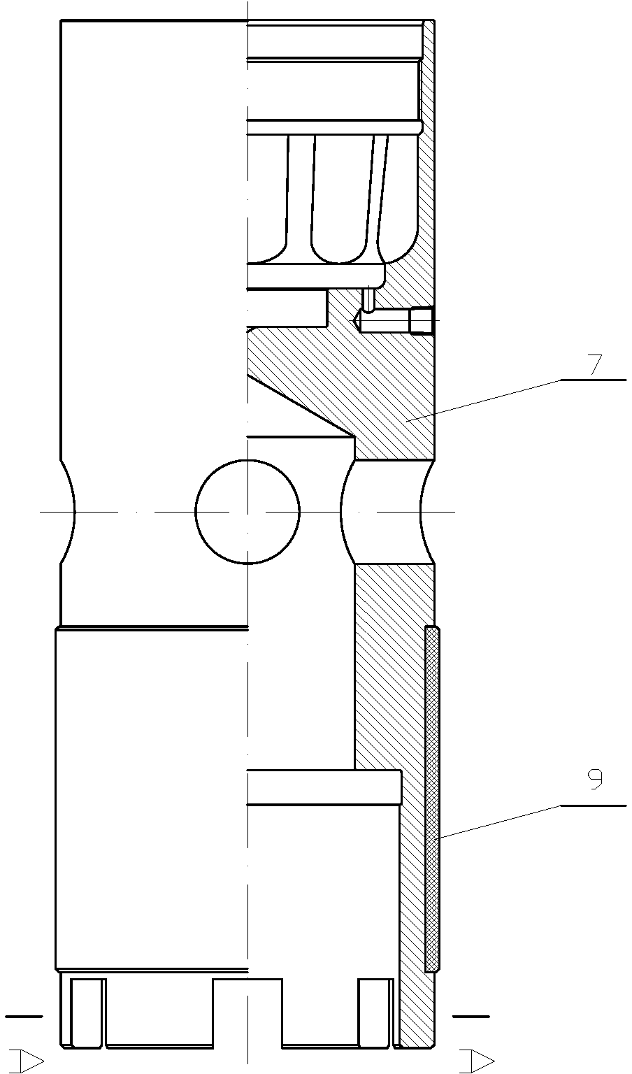
[0032] Such as figure 1 — Figure 12 The hydraulic oscillator of the present invention includes an upper joint 1, a stator 2, a casing 5 and a lower joint 13 which are sequentially sealed and connected, a rotor 3 is arranged eccentrically in the stator 2, and a cardan shaft is sequentially connected to the casing 5 at the lower end of the rotor 3. Joint 3, cardan shaft 6 and cardan shaft transmission rod 7, the outer circumference of the lower end of the cardan shaft transmission rod 7 is in sliding and sealing connection with the casing 5 through a sliding bearing component, the inner wall of the lower end of the casing 5 is in threaded connection with the lower joint 13, and the cardan shaft transmission The lower end of the rod 7 is matched with a vibrating valve 10, which can reciprocate and slide along the mating surface relative to the cardan shaft transmission rod 7. The lower end of the vibrating valve 10 is sealed with a moving valve plate 11 that operates synchronous...


PUM


Abstract

The invention relates to a waterpower oscillator through which effective pressure can be exerted on a drill bit and well drilling efficiency can be improved in the technical field of oil exploitation. The waterpower oscillator comprises an upper connector, a stator, an outer shell and a lower connector all of which are sequentially connected in a sealed mode. A rotor is eccentrically arranged inside the stator, and the lower end of the rotor is sequentially connected with a cardan shaft upper connector, a cardan shaft and a cardan shaft transmission rod. The lower end of the cardan shaft transmission rod is connected with the outer shell in a sealed mode, the lower end of the outer shell is in threaded connection with the lower connector in a sealed mode, the lower end of the cardan shaft transmission rod is provided with a vibration valve in a matched and sleeved mode, and the vibration valve can do reciprocating sliding motion along the matched surface relative to the cardan shaft transmission rod. The lower end of the vibration valve is provided with a movable valve plate in a sealed and sleeved mode, wherein the movable valve plate and the vibration valve can do the synchronous movement, the upper end of the lower connector is correspondingly provided with a fixed valve plate attached to the movable valve plate, the movable valve plate and the fixed valve plate are respectively provided with a sector channel with the area larger than that of a half circle. An annular hollow part through which liquid can flow is formed among the rotor, the cardan shaft upper connector, the cardan shaft, the stator and the outer shell, the cardan shaft transmission rod is provided with a channel communicated with the annular hollow part, and the channel is communicated with a vibration valve cavity and the sector channels.

Description

technical field [0001] The invention relates to the technical field of petroleum exploitation, in particular to a hydraulic oscillator which can effectively increase the drilling pressure of a drill bit in the exploitation of complex-structured wells such as highly deviated wells and horizontal wells, so as to improve drilling speed and production efficiency. Background technique [0002] With the development of highly deviated wells, horizontal wells and lateral lateral wells in major oilfields in my country, how to effectively apply WOB to the bit has become a common concern. At present, there are mainly two drilling methods: compound drilling and sliding drilling with downhole power tools. Due to the increase of hydraulic loss along the way of these complex structures, the available water horsepower of the bottom hole drill bit is quite low, and generally the weight of the drill string is applied to the drill bit to break the rock. However, in the drilling construction o...

Claims


Application Information

Patent Timeline
Patent Type & Authority Applications(China)
IPC IPC(8): E21B7/24
Inventor 祝兆清常青忠王端痒
Owner YANGZHOU TIANYE GASOLINEEUM MACHINERY
Why Eureka
Try Eureka