
3D imaging device

An image capture, 3D technology, applied in image communication, photography, stereo photography, etc.

Inactive Publication Date: 2013-11-27
FUJIFILM CORP
View PDF8 Cites 4 Cited by
  • Summary
  • Abstract
  • Description
  • Claims
  • Application Information

AI Technical Summary

Problems solved by technology

However, if the offset in the left-right direction corresponding to the parallax is insufficient, a good 3D image cannot be obtained by reproducing the left-eye image and the right-eye image

Method used


Image

  • 3D imaging device
  • 3D imaging device
  • 3D imaging device

Examples


Embodiment Construction

[0032] Hereinafter, embodiments of the present invention will be described with reference to the accompanying drawings.

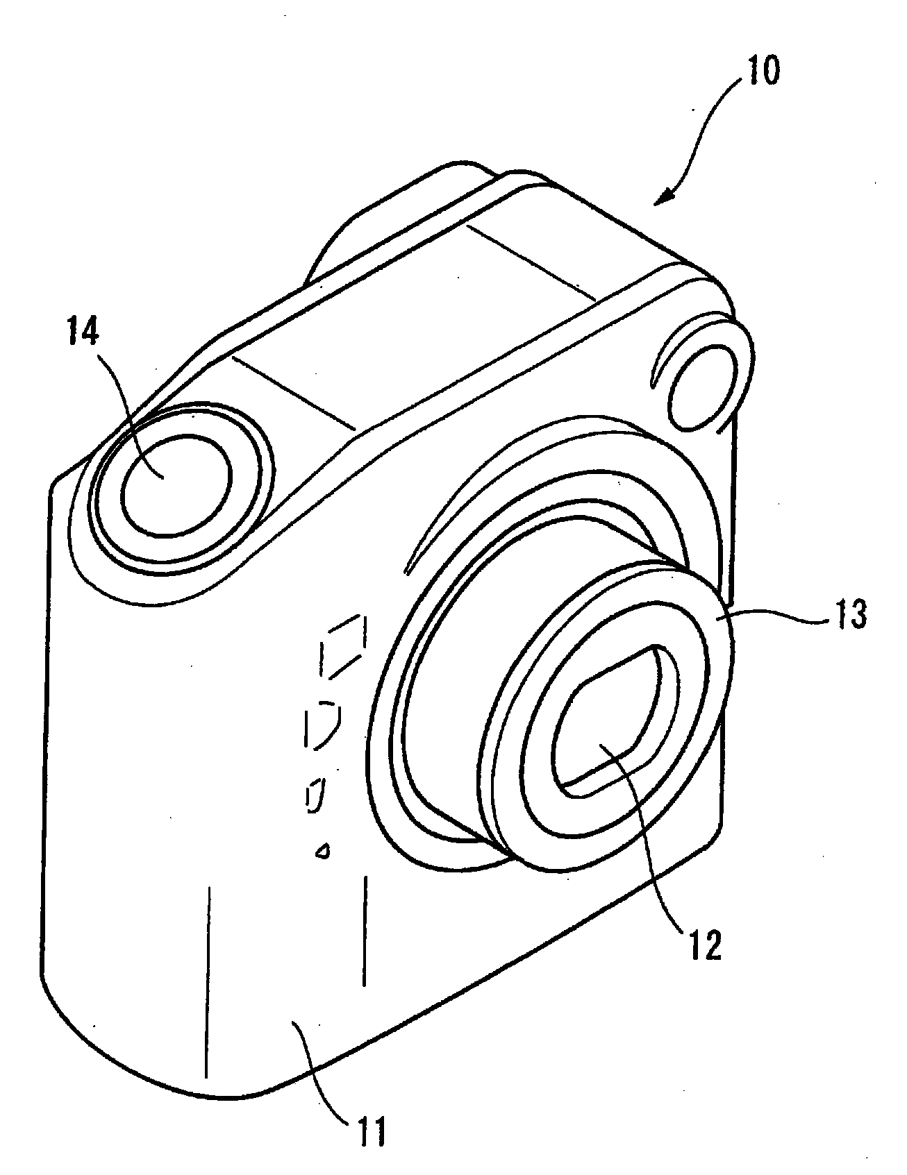
[0033] figure 1 is a perspective view of a digital camera capable of capturing 3D images according to an embodiment of the present invention. In the digital camera 10 , a monocular photographic lens 12 is arranged on the front side of a rectangular main body 11 . The photographic lens 12 is provided in a lens barrel 13 that can be retracted into the main body 11 . The main body 11 is provided with a shutter release button 14 at the upper right corner.

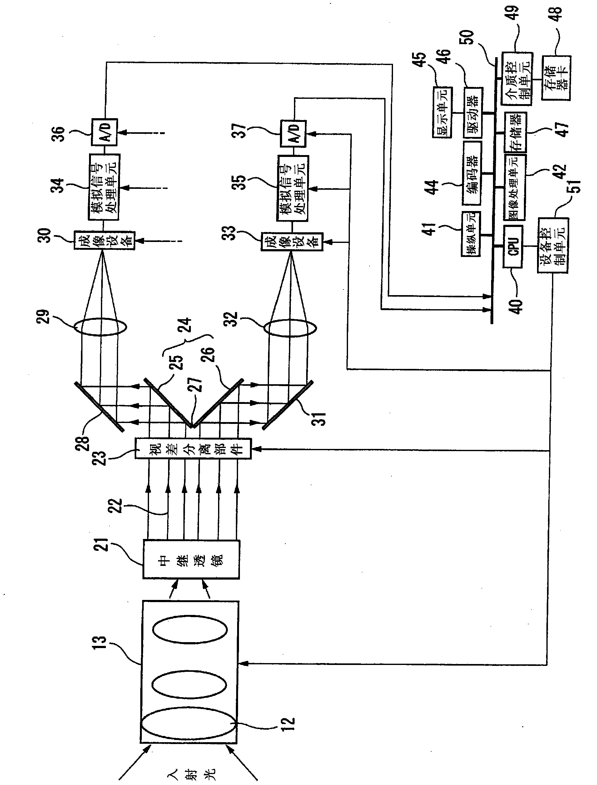
[0034] figure 2 is showing figure 1 A block diagram of the functional configuration of the digital camera 10. The digital camera 10 is equipped with a lens barrel 13 housing a photographic lens 12 . The lens barrel 13 accommodates a focus adjustment lens, a telephoto lens, and the like in addition to the photographic lens 12 .

[0035] The relay lens 21 is arranged behind the lens barrel 13 . Inci...


PUM


Abstract

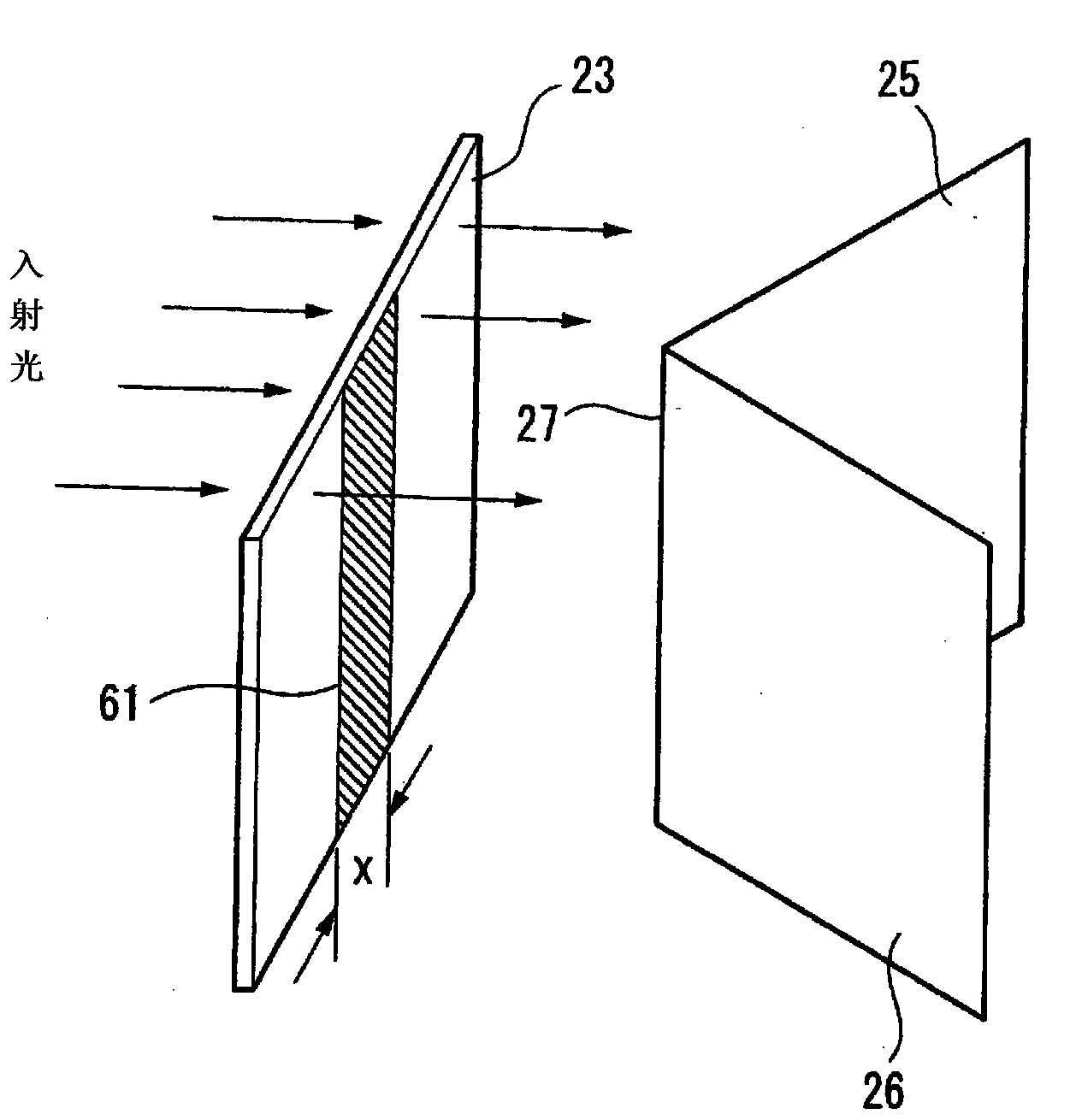
Provided is a 3D imaging device that can take good 3D images using a single lens. Said 3D imaging device is provided with: a single imaging lens (12); first and second solid-state imaging elements (30 and 33) that, in parallel, receive incident light that comes from a subject and passes through the imaging lens (12); a beam-splitting means (24) that splits the incident light along a boundary line perpendicular to the optical axis thereof, inputs one of the resulting light beams to one of the solid-state imaging elements (30), and inputs the other resulting light beam to the other solid-state imaging element (33); a parallax-separation means (23) that prevents incident light from the aforementioned boundary line from reaching the solid-state imaging elements (30 and 33); and an image-processing means (41) that generates 3D image data of the subject by performing image processing on output signals from the solid-state imaging elements (30 and 33).

Description

technical field [0001] The invention relates to a 3D image capturing device. More specifically, the present invention relates to a monocular 3D image capture device capable of achieving satisfactory left / right separation of parallax. Background technique [0002] TV receivers capable of displaying 3D images have been widely used, and there are signs that digital cameras (3D image capture devices) capable of capturing 3D images of subjects are spreading. [0003] As disclosed in, for example, Patent Document 1 (see below), a conventional 3D image capture device is a binocular type and is equipped with two imaging lens systems arranged on the front side of a camera body and aligned in the horizontal direction. The photographic lens systems located on the left and right sides (as viewed from the front side) correspond to the right and left eyes of humans, respectively. The left and right photographic lens systems are separated by about 6.5 cm, which is the average distance be...

Claims


Application Information

Patent Timeline
Patent Type & Authority Applications(China)
IPC IPC(8): G03B35/08H04N5/225H04N13/02
CPCH04N5/2254G03B35/10H04N13/0239G02B27/14H04N13/239H04N23/55
Inventor 岩崎洋一
Owner FUJIFILM CORP
Learn More