Method and device for controlling the temperature of plastic mass

A plastic and temperature-adjusting technology, which is used in the field of temperature-adjusting equipment for plastic materials, and can solve problems such as difficult operation of methods and technologies.

Active Publication Date: 2013-12-04
BATTENFELD CINCINNATI GERMANY GMBH
View PDF7 Cites 2 Cited by
  • Summary
  • Abstract
  • Description
  • Claims
  • Application Information

AI Technical Summary

Problems solved by technology

[0005] However, such molds are method-technically difficult to operate, since the flow behavior of the cooled single strands has to be coordinated with one another

Method used


Image

  • Method and device for controlling the temperature of plastic mass
  • Method and device for controlling the temperature of plastic mass
  • Method and device for controlling the temperature of plastic mass

Examples


Embodiment Construction

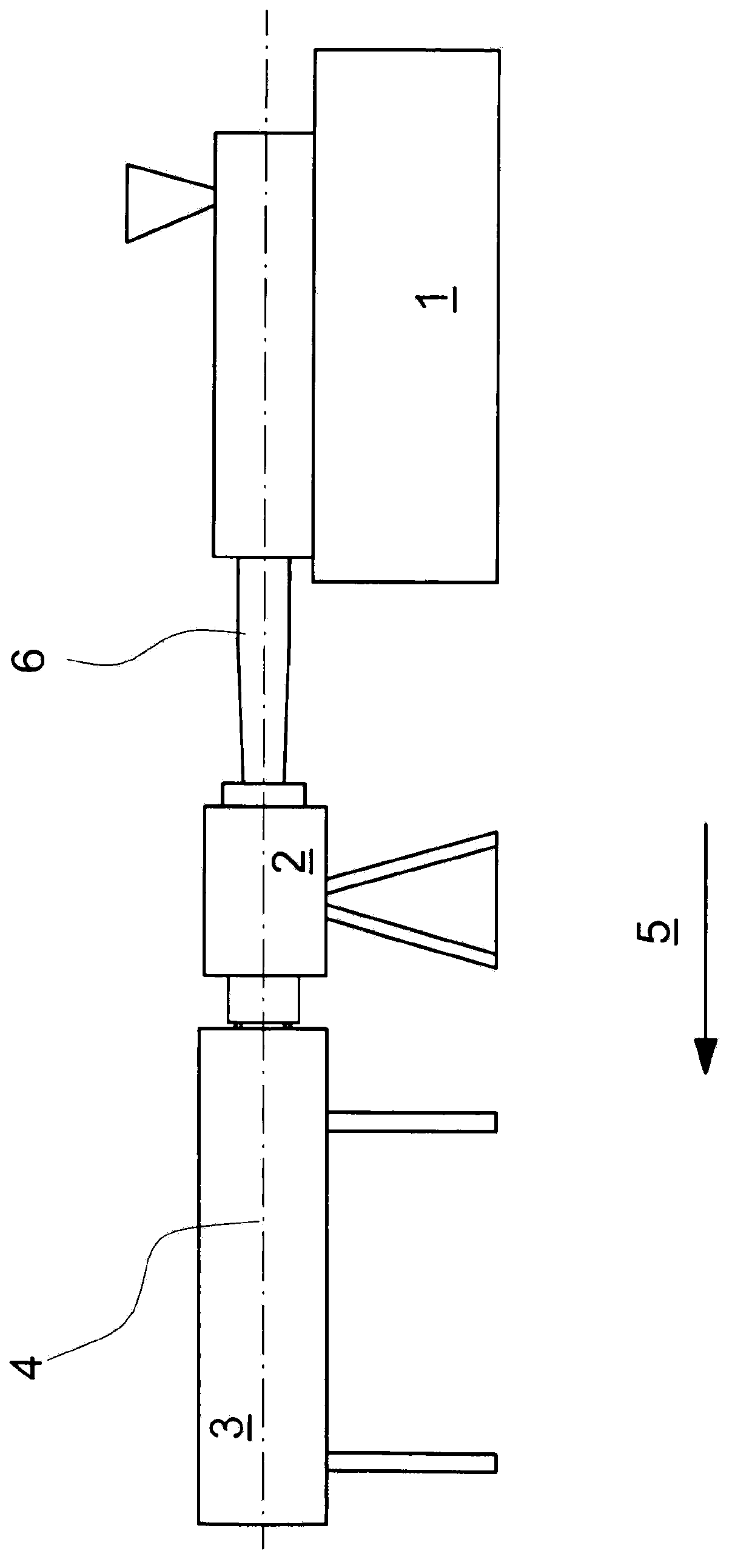
[0039] exist figure 1 An extrusion line is schematically shown in , wherein an extruder 1 is arranged on an extrusion die 2 . Viewed in the extrusion direction 5 , a calibration device (Kalibrierung) 3 is attached to the die 2 . Further subsequent devices (Nachfolgeeinrichtung), such as a cooling device, extraction device (Abzug) and separation device (not shown), are connected thereto. The plastic tube 6 is produced in the extrusion line shown as an example. The calibration device 3 may comprise a vacuum box with a calibration sleeve inserted. Other cooling baths can also be connected to the calibration unit. The extrusion axis is shown with position number 4. The direction of extrusion is at the same time the direction of melt flow.

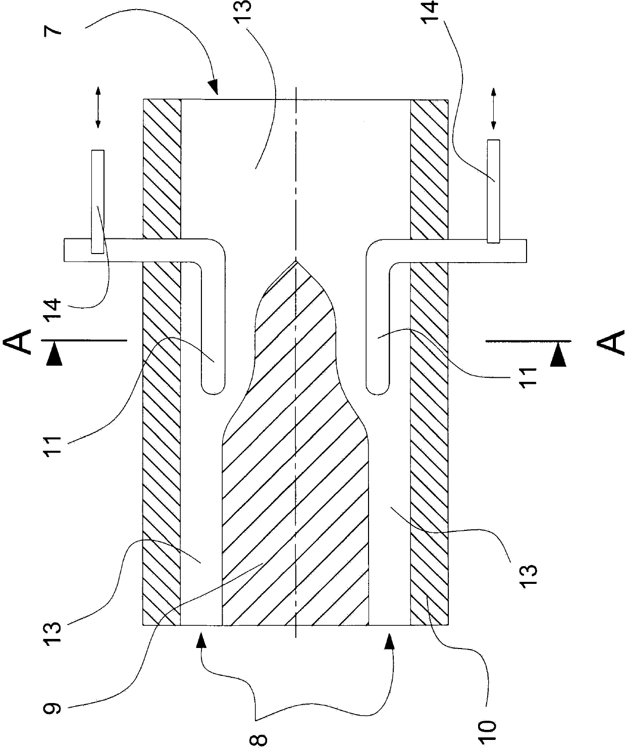
[0040] figure 2The die is shown in a sectional view, wherein the section runs in the middle and along the extrusion axis 5 . A temperature control element is shown schematically between the melt inlet 7 and the melt outlet 8 . The melt...


PUM


Abstract

A method for controlling the temperature of a polymer melt in an extrusion tool includes flowing the polymer melt via at least one flow channel from an input to an output and around at least one temperature-control element in the at least one flow channel. The temperature control element includes a plurality of temperature control units. The temperature of the polymer melt flowing around the temperature-control element is controlled by individually controlling each of the temperature-control units so as to vary a degree of temperature control of the temperature-control element such that a degree of temperature control is controllable to be the same or different at locations throughout the temperature control-element.

Description

technical field [0001] The invention relates to a method for tempering a mouldable plastic mass in an extrusion die, in particular a pipe extrusion die, wherein the plastic mass is passed from at least one melt inlet to at least one melt via one or more flow channels The melt outlet flows, wherein the plastic mass between the melt inlet and the melt outlet flows around at least one temperature control element in the flow channel. and a device related thereto. Background technique [0002] What is required for the production of the tube is that the cylindrical plastic melt stream produced by the extruder is transformed into a ring-shaped gap ( ) melt flow. What is essential for this is that the melt flow coming from the extruder is converted into a corresponding annular flow in the die by means of the centrally arranged mandrel. Such a device is proposed in DE10315906. [0003] Short extrusion lines (Extrusionslinie) are now often required. This can only be achieved if ...

Claims


Application Information

Patent Timeline
Patent Type & Authority Applications(China)
IPC IPC(8): B29C47/90B29C48/09B29C48/32B29C48/325B29C48/445B29C48/90B29C48/92
CPCB29C47/864B29C47/0811B29C47/92B29C2947/92904B29C47/882B29C2947/92704B29C47/866B29C47/862B29C47/78B29C47/0023B29C2947/92971B29C2947/92209B29C47/22B29C47/20B29C48/10B29C48/87B29C48/92B29C48/325B29C48/832B29C48/834B29C48/865B29C48/872B29C48/919B29C48/9115B29C48/09B29C48/905B29C2948/92209B29C2948/92704B29C2948/92904B29C2948/92971B29C48/705B29C48/2556B29C48/78B29C48/32
Inventor T·格施佩
Owner BATTENFELD CINCINNATI GERMANY GMBH
Why Eureka
Try Eureka