Method for producing improved ZVT PWM converter auxiliary drives

An auxiliary drive and converter technology, applied in the direction of output power conversion devices, electrical components, etc., can solve the problems of the main switch tube drive phase difference

Inactive Publication Date: 2013-12-11
THE 724TH RES INST OF CHINA SHIPBUILDING IND
View PDF1 Cites 0 Cited by
  • Summary
  • Abstract
  • Description
  • Claims
  • Application Information

AI Technical Summary

Problems solved by technology

Therefore, the auxiliary switching tube only works for a short period of time in the entire working cycle, an

Method used


Image

  • Method for producing improved ZVT PWM converter auxiliary drives
  • Method for producing improved ZVT PWM converter auxiliary drives

Examples


Embodiment Construction

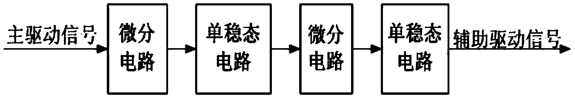
[0009] The specific implementation steps of the application method of the monostable circuit of the present invention in the converter auxiliary drive generation circuit can be found in figure 1 :

[0010] ① Through the first monostable circuit, a pulse signal with adjustable pulse width is obtained by using the falling edge of the differentiated signal of the main drive;

[0011] ② Through the second monostable circuit, the auxiliary drive is obtained by using the falling edge of the differentiated pulse signal;

[0012] ③ Adjust the phase and pulse width of the auxiliary drive to meet the working requirements of the converter;

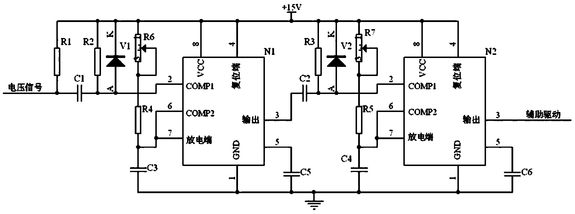
[0013] The application method of the monostable circuit of the present invention in the auxiliary drive generation circuit of the converter is shown in the schematic diagram of the circuit figure 2 , N1 and N2 in the figure are 555 timers.

[0014] ① After the main drive signal passes through the differential circuit C1 and R2, it is introduced b...


PUM


Abstract

The invention relates to a method for producing improved ZVT PWM converter auxiliary drives. According to the method, monostable circuits are utilized to perform phase position movement and adjustment on main switch tube driving signals, therefore, auxiliary switch tube drives capable of being adjusted in phase position and pulse width can be obtained, and work requirements of improved ZVT PWM converters are met. As is shown in the figure, according to the functional block diagram of the application method, the processing flow includes the steps that firstly, through the first monostable circuit, a pulse signal adjustable in pulse width is obtained by the utilization of signal falling edges after master drive differential; then, the auxiliary drives are obtained through the second monostable circuit. The phase position and the pulse width of each auxiliary drive can both be adjusted, auxiliary switch tubes of the improved ZVT PWM converters can be opened in advance of a main switch tube, the zero voltage condition is created for opening the main switch tube, then, the auxiliary switch tube is closed, the main switch tube works in a mode same as PWM, and the work requirements of the improved ZVT PWM converters are met.

Description

technical field [0001] The invention belongs to the technology of special power supply, and is a method for generating auxiliary driving of an improved ZVT PWM converter. . Background technique [0002] The improved ZVT PWM converter creates a ZVS (zero voltage switching) condition for the main switching tube through the auxiliary resonant network, and the main switching tube is turned on and off under zero voltage state, which greatly reduces the reactive power loss of the main switching tube. The auxiliary switching tube itself is also turned on at zero current and turned off at zero voltage, and is in a soft switching state, and the main freewheeling diode is also naturally turned off under the condition of zero current. [0003] In normal operation, the auxiliary switching tube is turned on before the main switching tube to create a zero-voltage condition for the main switching tube to be turned on. After the main switching tube is turned on, the auxiliary switching tub...

Claims


Application Information

Patent Timeline
IPC IPC(8): H02M1/08
Inventor 杨香兵蔡宝龙
Owner THE 724TH RES INST OF CHINA SHIPBUILDING IND
Why Eureka
Try Eureka