
Travel velocity compensation apparatus and method for railway vehicles

A technology for railway vehicles and driving speed, which is applied in the field of driving speed compensation devices, which can solve problems such as poor accuracy, large errors, and inability to calculate the speed of railway vehicles, and achieve the effect of improving accuracy and removing external noise

Active Publication Date: 2013-12-18
LSIS CO LTD
View PDF3 Cites 5 Cited by
  • Summary
  • Abstract
  • Description
  • Claims
  • Application Information

AI Technical Summary

Problems solved by technology

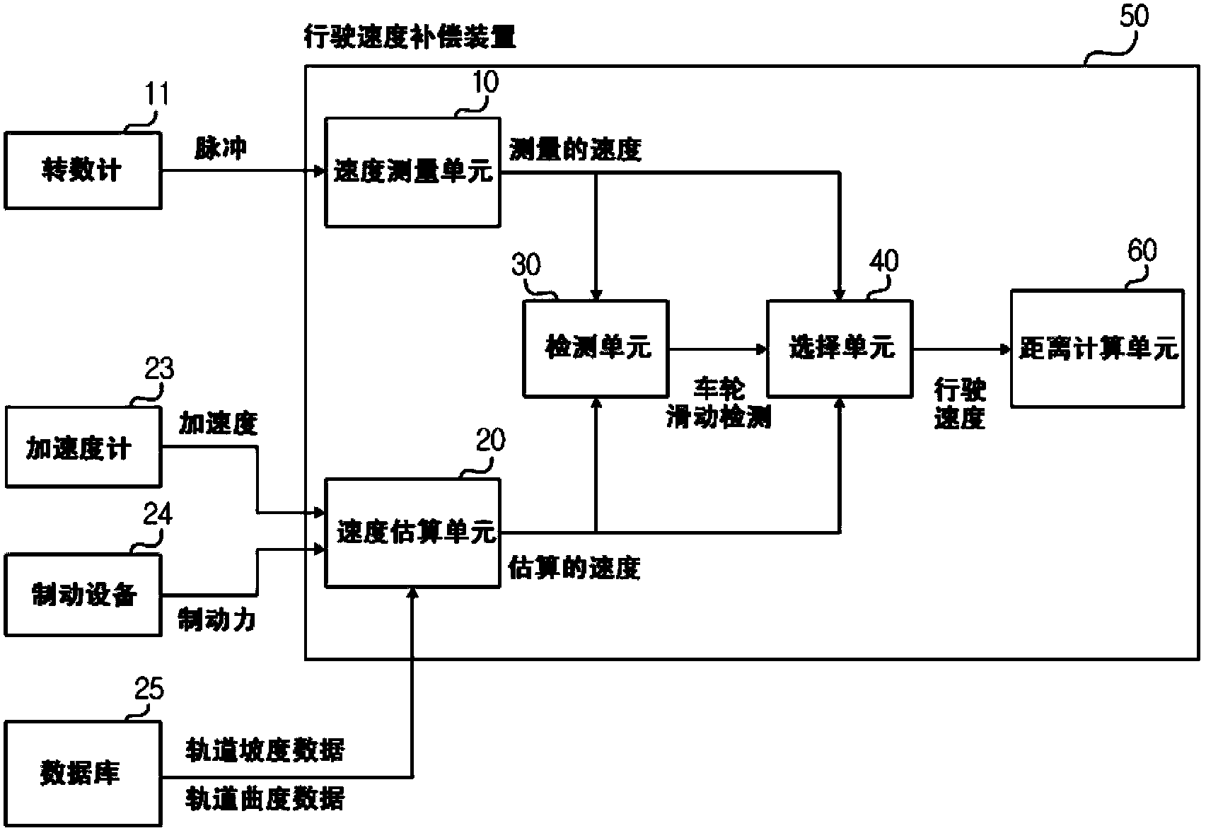
[0007] However, a problem arises in that it is not possible to use the angular velocity of the wheel to calculate the speed of the railway vehicle in the case where the wheel slip occurs because the wheel slips due to the locked state of the wheel
That is, in the event of slippage, the wheels do not rotate so that the calculated speed of the railway vehicle is zero (0), which in turn causes a large error in the calculation of the speed of the railway vehicle
[0008] The method of obtaining the traveling speed of the railway vehicle by integrating the acceleration information measured by the accelerometer has the disadvantage that during the calculation of the speed of the railway vehicle, noise from the sensor is also integrated during the measurement, resulting in poor accuracy

Method used


Image

  • Travel velocity compensation apparatus and method for railway vehicles
  • Travel velocity compensation apparatus and method for railway vehicles
  • Travel velocity compensation apparatus and method for railway vehicles

Examples


Embodiment Construction

[0045] Various exemplary embodiments will be described more fully hereinafter with reference to the accompanying drawings, in which some exemplary embodiments are shown. However, the inventive concept can be embodied in many different forms and should not be construed as limited to the exemplary embodiments set forth herein. Rather, the described scheme is intended to embrace all such alterations, modifications and changes that fall within the scope and novelty of the present disclosure.

[0046] It will be understood that although the words first, second, third etc. may be used herein to describe various elements, components, regions, layers and / or sections, that these elements, components, regions, layers and / or Parts should not be limited by these words. These terms are only used to distinguish one element, component, region, layer or section from another region, layer or section. Thus, a first element, component, region, layer or section discussed hereinafter could be te...


PUM


Abstract

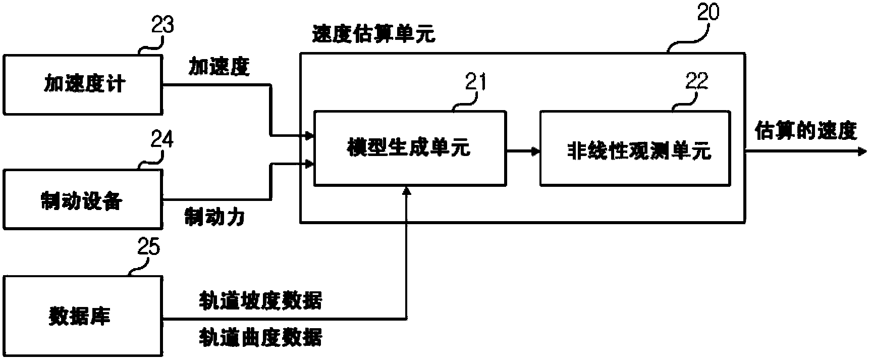
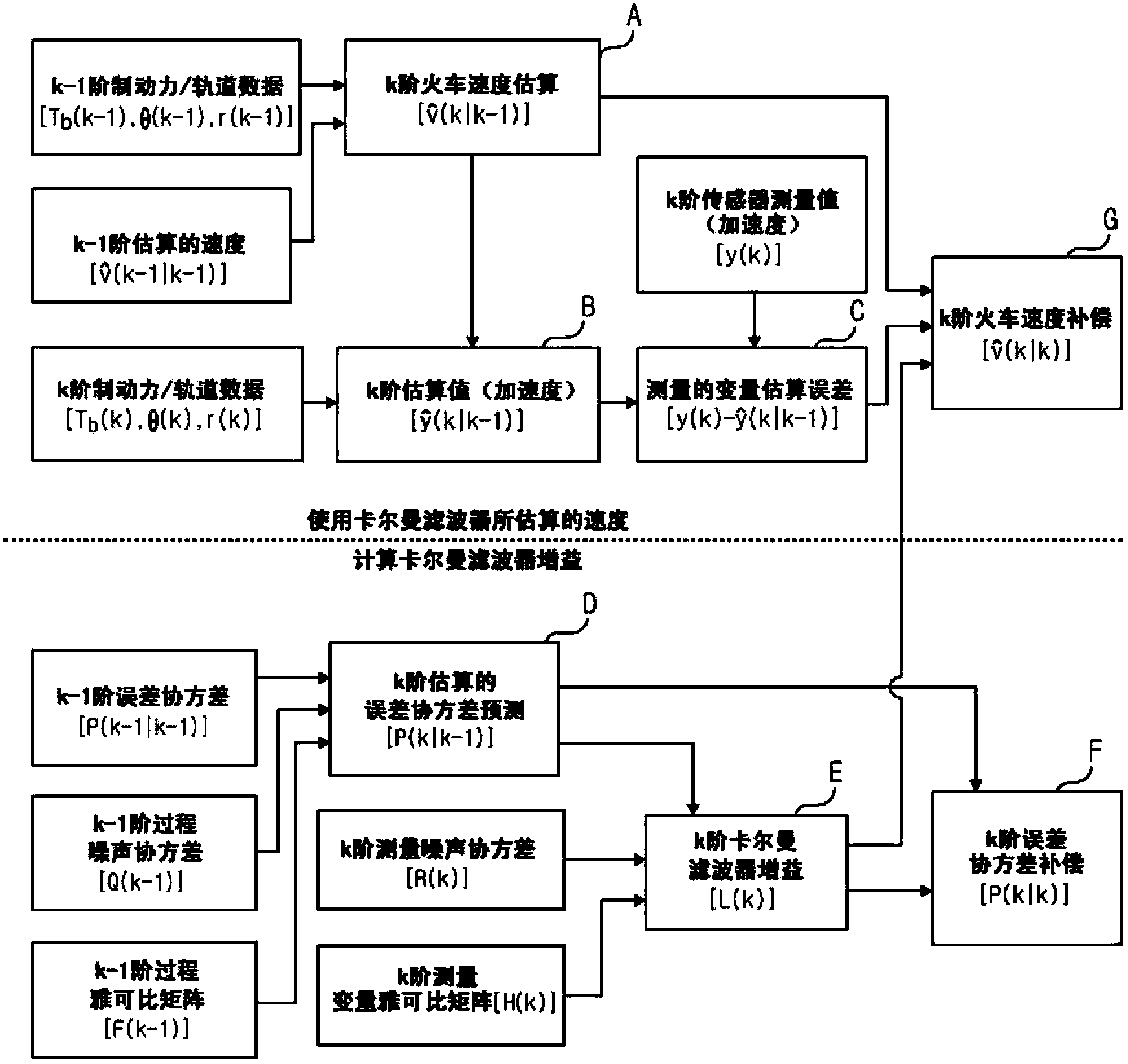
Disclosed is a travel velocity compensation apparatus for railway vehicles and a method thereof for compensating a travel velocity when there is generated a slide between a wheel and a railway, the apparatus including a velocity measurement unit measuring a travel velocity of a railway vehicle, a velocity estimation unit estimating the travel velocity using travel information of railway vehicle and rail information received from at least one sensor, a detection unit generating wheel slide information by determining whether wheels of the railway vehicle slide, using the travel velocity of the railway vehicle measured by the velocity measurement unit and the travel velocity estimated by the velocity estimation unit, and a selection unit selecting, as a travel velocity, any one of the travel velocity measured by the velocity measurement unit using the wheel slide information generated by the detection unit and the travel velocity estimated by the velocity estimation unit.

Description

technical field [0001] The present disclosure relates to a traveling speed compensating device for a railway vehicle and a method thereof, and more particularly to a device and a method for compensating a traveling speed of a railway vehicle during slippage between wheels and rails of the railway vehicle. Background technique [0002] Generally, the wheels and rails of a railway vehicle are all made of steel material, and a sliding (or jumping) phenomenon is prone to occur during braking of the railway vehicle due to a small adhesion coefficient between the wheel and the rail. In the case where the braking force is greater than the coefficient of adhesion between the wheels of the railway vehicle and the rails, a slipping phenomenon occurs at a position where the wheels do not rotate but slip due to the locked state of the wheels. Therefore, in the event of slipping, the braking distance of the railway vehicle is prolonged so that the wheels are worn due to friction between ...

Claims


Application Information

Patent Timeline
Patent Type & Authority Applications(China)
IPC IPC(8): G01P3/00
CPCB61C15/08B61C15/12B60L3/08B60L15/40
Inventor 郑锺哲赵镛纪
Owner LSIS CO LTD
Learn More