
Brake mechanism and speed reduction mechanism

A technology of deceleration mechanism and braking mechanism, applied in the direction of gear shifting mechanism, program control manipulator, manipulator, etc., can solve problems such as danger

Pending Publication Date: 2021-08-20
NABLESCO CORP
View PDF0 Cites 0 Cited by
  • Summary
  • Abstract
  • Description
  • Claims
  • Application Information

AI Technical Summary

Problems solved by technology

[0002] In industrial robots, machine tools, etc., when the machine stops due to some abnormality such as emergency stop or power failure, it is dangerous if it cannot maintain its posture and hangs down due to its own weight.

Method used


Image

  • Brake mechanism and speed reduction mechanism
  • Brake mechanism and speed reduction mechanism
  • Brake mechanism and speed reduction mechanism

Examples


Embodiment Construction

[0105] Hereinafter, a first embodiment of the speed reducer according to the present invention will be described based on the drawings.

[0106] In addition, in each drawing used in the following description, in order to make each member into a recognizable size, the scale of each member is changed suitably. Dimensions and ratios of each component are suitably different from actual ones.

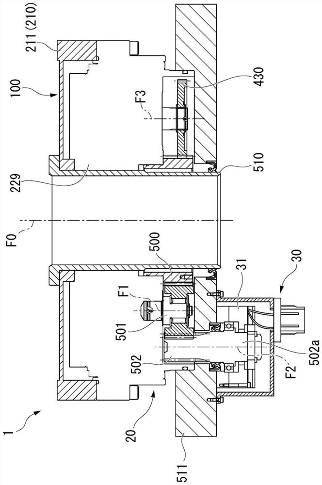
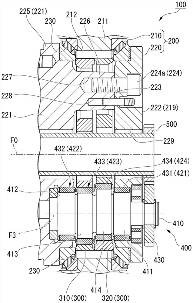
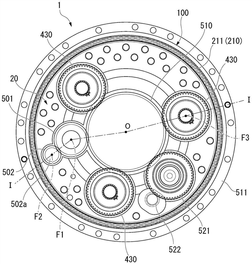
[0107] figure 1 is a schematic cross-sectional view along the axial direction showing the reduction mechanism of the present embodiment, figure 2 is a cross-sectional view showing the speed reduction unit of the speed reduction mechanism according to the present embodiment viewed along the axial direction, image 3 It is a schematic cross-sectional view along the axial direction showing a speed reduction portion of the speed reduction mechanism in this embodiment, and in the figure, reference numeral 1 denotes a speed reduction mechanism.

[0108] Such as figure 1 , figure 2 As show...


PUM


Abstract

The invention provides a brake mechanism and a speed reduction mechanism. This speed reduction mechanism is provided with: a speed reduction unit that reduces an input rotational speed; a speed increasing unit that increases the rotational speed output from the speed reducing unit; and a brake unit that applies a braking force for braking the speed increasing unit.

Description

technical field [0001] The present invention relates to a brake mechanism and a deceleration mechanism, and particularly relates to a technology suitable for use in a mechanism equipped with a brake and a decelerator. Background technique [0002] In industrial robots, machine tools, etc., it is dangerous if they cannot maintain their posture and hang down due to their own weight when they stop due to some abnormality such as emergency stop or power failure. Therefore, in general, a robot or the like is provided with a brake for maintaining the posture. [0003] As such an example, as described in Patent Document 1, it is known that the drive unit 10 provided in the first articulated body 3 of the robot 1 has the following components: a motor 20; Shaft 29 is arranged in parallel; Pulley mechanism 40, it connects output shaft 29 and one end 25a of brake shaft 25 and transmits the rotation of motor 20 to brake shaft 25; And electromagnetic brake 21 and speed reducer 22, it an...

Claims


Application Information

Patent Timeline
IPC IPC(8): F16H57/10
CPCF16H57/10F16H2057/02069F16H2057/02086F16H1/32F16H2001/323B25J9/102B25J19/0004F16D2121/22F16H7/02F16H7/06
Inventor 内原正登永原康平中村江児长屋雄太岛本光
Owner NABLESCO CORP
Learn More