Display device for working machine

A technology of operating machinery and display devices, applied in the field of display devices, can solve problems such as fuel consumption without special consideration

Active Publication Date: 2016-01-06
NIHON KENKI CO LTD
View PDF5 Cites 0 Cited by
  • Summary
  • Abstract
  • Description
  • Claims
  • Application Information

AI Technical Summary

Problems solved by technology

However, in the prior art mentioned above, the fuel consumption in the idling state is not particularly considered, and there is room for improvement in this regard.

Method used


Image

  • Display device for working machine
  • Display device for working machine
  • Display device for working machine

Examples


no. 1 Embodiment approach >

[0028] refer to Figure 1 to Figure 6 and Figure 9 The first embodiment of the present invention will be described.

[0029] Figure 9 It is an external view showing a hydraulic excavator shown as an example of the working machine of the present embodiment.

[0030] exist Figure 9 Among them, a hydraulic excavator (working machine) is roughly constituted by a crawler-type undercarriage 1, an upper revolving unit 2 provided so as to be rotatable relative to the undercarriage 1, and a front working machine 3 having an excavation mechanism and the like. .

[0031] A pair of left and right traveling hydraulic motors (not shown) are disposed on the undercarriage 1 , and each crawler belt is independently rotationally driven by the traveling hydraulic motor and its speed reduction mechanism to travel forward or backward.

[0032] The upper revolving body 2 has: an operating device 6 for performing various operations of the hydraulic excavator; a cab 4 such as a driver's seat ...

no. 2 Embodiment approach >

[0069] refer to Figure 7 and Figure 8 A second embodiment of the present invention will be described. In the drawings, the same reference numerals are assigned to the same components as those in the first embodiment, and description thereof will be omitted.

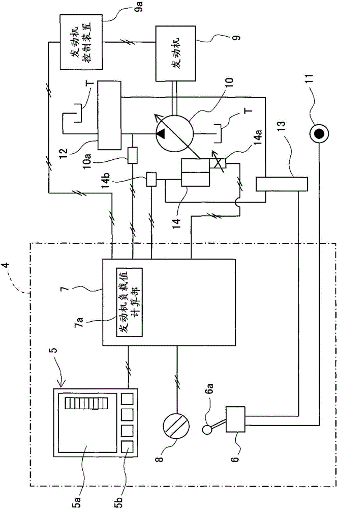
[0070] Figure 7 It is a figure which shows the outline of the hydraulic excavator of this embodiment together with the display device 5 and its peripheral structure.

[0071] Such as Figure 7 As shown, the cab 4 of the hydraulic excavator is provided with: a body controller 7A for controlling the movement of the whole body; and a display for displaying various information related to the hydraulic excavator according to signals from the body controller 7A. device 5; an engine control dial (EC dial) 8 indicating the rotational speed of the engine 9 as a prime mover to the body controller 7A; and a plurality of (in this embodiment One is shown in the way as a representative) operating device 6.

[0072] In addition...


PUM


Abstract

A display device (5) for a work machine comprising: an engine (9); a hydraulic pump (10) driven by the engine (9); a power pump driven by hydraulic oil supplied from the hydraulic pump (10); Arm hydraulic cylinder (3d), stick hydraulic cylinder (3e), bucket hydraulic cylinder (3f) and other actuators; and the operating device (6) for operating the actuators (3d, 3e, 3f), in The display device of the work machine has an idling state display unit (50a) that displays the engine speed N as non-operating operating state information that is related to the non-operating engine load of the operating device (6). associated information. Accordingly, by notifying the operator of the state of the engine load in the idling state, it is possible to promote the transition to a state with good fuel economy.

Description

technical field [0001] The present invention relates to a display device of working machines such as hydraulic excavators. Background technique [0002] On a display device installed in a cab of a work machine such as a hydraulic excavator, various instruments and body information are displayed so that an operator can check the state of the work machine. One of the information displayed on such a display device is the fuel consumption information of the work vehicle. A fuel consumption calculation unit that calculates fuel consumption, and a fuel consumption display unit that displays whether the fuel consumption calculated by the fuel consumption calculation unit is above the target fuel consumption (see Patent Document 1, etc.). [0003] prior art literature [0004] patent documents [0005] Patent Document 1: Japanese Patent Laid-Open No. 2008-62791 [0006] In the prior art described above, the fuel consumption is displayed in real time by the length of the indicato...

Claims


Application Information

Patent Timeline
Patent Type & Authority Patents(China)
IPC IPC(8): E02F9/26
CPCE02F9/2066E02F9/2296E02F9/26
Inventor 西川真司石川广二大木孝利中村惠一郎
Owner NIHON KENKI CO LTD
Why Eureka
Try Eureka