
Pneumatic hydraulic jack with no-load quick lift function

A pneumatic hydraulic jack technology, applied in the field of hydraulic jacks, can solve the problems of low work efficiency, waste of compressed air, slow rising speed, etc., and achieve the effect of improving work efficiency and safety performance

Inactive Publication Date: 2015-12-23
衡阳市锦泰工具有限公司
View PDF7 Cites 5 Cited by
  • Summary
  • Abstract
  • Description
  • Claims
  • Application Information

AI Technical Summary

Problems solved by technology

The existing pneumatic hydraulic jack has the same rising speed in the two stages of no-load rising and load rising, and the rising speed is also very slow when it is no-load, which wastes time and energy and has low work efficiency
[0004] In addition, in order to improve the working efficiency of the jack, various manufacturers often design the air intake hole of the pneumatic booster to be very large to speed up the movement frequency of the pneumatic booster in an attempt to increase the pumping speed, but the actual effect is not obvious. On the contrary, it causes a lot of waste of compressed air, which eventually leads to a waste of energy.

Method used


Image

  • Pneumatic hydraulic jack with no-load quick lift function
  • Pneumatic hydraulic jack with no-load quick lift function
  • Pneumatic hydraulic jack with no-load quick lift function

Examples


Embodiment Construction

[0021] The present invention will be further described in detail below in conjunction with specific embodiments and drawings.

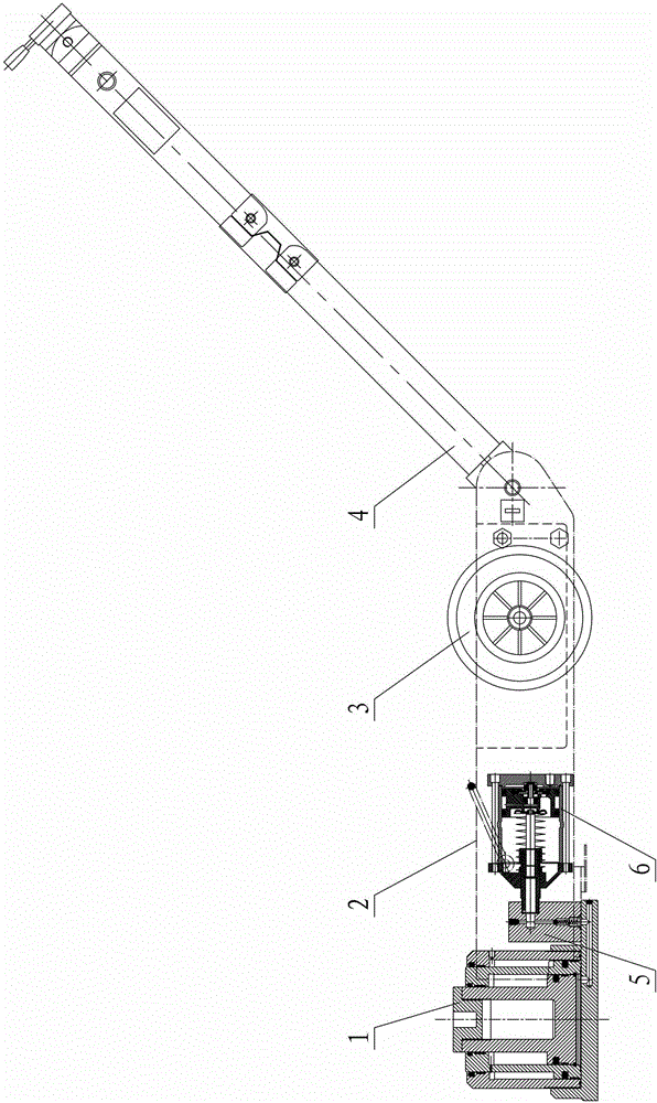
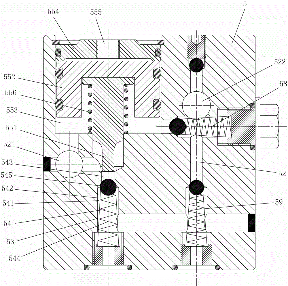
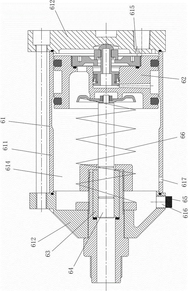
[0022] Such as figure 1 , figure 2 As shown, the pneumatic hydraulic jack with no-load fast lifting function of this embodiment includes a frame 2 and a fuel tank (not shown) installed on the frame 2, a lifting cylinder 1, a pneumatic booster 6, and wheels 3. , Operating lever 4 and transition plate 5. The operating rod 4 is mainly used for people to push the jack to walk, and the operating rod 4 is provided with switches and handles for controlling the start, stop, and lift of the jack. The oil tank is connected to the jacking cylinder 1 through the oil supply path 52 on the transition plate 5, and the hydraulic oil is pumped into the jacking cylinder 1 through the pneumatic booster 6 connected to the oil supply path 52. The oil supply path 52 is provided with a first check valve 58, a second check valve 59, an oil inlet pipe interface 521 for connect...


PUM


Abstract

The invention discloses a pneumatic hydraulic jack with a no-load fast jacking function. The jack comprises a jacking oil cylinder, an oil tank, a transition plate and a pneumatic booster; the oil tank is connected with the jacking oil cylinder by an oil supplying oil path on the transition plate and pumps hydraulic oil into the jacking oil cylinder by the pneumatic booster connected onto the oil supplying oil path; the oil supplying oil path is connected with a pressure releasing oil path flowing back to the oil tank; the pressure releasing oil path is provided with a pressure releasing check valve only unidirectionally opened along the direction from the oil tank to the jacking oil cylinder; the pneumatic booster comprises a cylinder drum and a pressure piston; the pressure piston is arranged in the cylinder drum and divides the interior of the cylinder drum into a rod cavity and a rodless cavity; an air inlet hole is formed in the rodless cavity; a pressure releasing vent hole is connected with the rod cavity connected with an air vent; the air vent is connected with the oil tank by an air pipe. The pneumatic hydraulic jack with the no-load fast jacking function has the advantages of simple structure, low cost, high work efficiency and the like.

Description

Technical field [0001] The present invention mainly relates to the field of hydraulic jacks, in particular to a pneumatic hydraulic jack with no-load fast lifting function. Background technique [0002] Pneumatic hydraulic jacks generally include a jacking cylinder, a fuel tank, a transition plate and a pneumatic booster. The fuel tank is connected to the jacking cylinder through the oil supply path on the transition plate, and the hydraulic oil is pumped in through the pneumatic booster connected to the oil supply path. Lifting cylinder. [0003] When the pneumatic hydraulic jack is working, it first rises for a certain distance without load, and then the load rises after it hits the car. The existing pneumatic hydraulic jacks have the same rising speed during the two stages of no-load rise and load rise, and the rise speed is also very slow when no-load, which wastes time and energy and has low work efficiency. [0004] In addition, in order to improve the working efficiency of t...

Claims


Application Information

Patent Timeline
Patent Type & Authority Patents(China)
IPC IPC(8): B66F3/24B66F3/25
Inventor 彭双喜
Owner 衡阳市锦泰工具有限公司
Learn More