

Fault diagnosis method for gear of drive system based on vibration signal analysis
A vibration signal and fault diagnosis technology, which is applied in the processing of detection response signals and the use of acoustic wave emission technology for material analysis. It can solve problems such as modal aliasing and achieve good fault diagnosis results.
Inactive Publication Date: 2013-12-25
SHANGHAI UNIVERSITY OF ELECTRIC POWER
View PDF0 Cites 10 Cited by
- Summary
- Abstract
- Description
- Claims
- Application Information
AI Technical Summary
Problems solved by technology
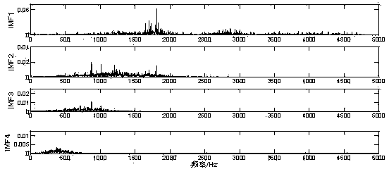
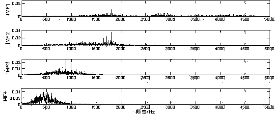
[0005] The present invention is to solve the problem of modal aliasing in the decomposition process of the traditional Empirical Mode Decomposition (EMD) method, so that the frequencies of the intrinsic mode components (IMF) of each order are arranged from high to low, so that the decomposition results It can better reflect the characterist
Method used
View moreImage
Smart ImageViewing Examples

Examples
 PUM
 Abstract
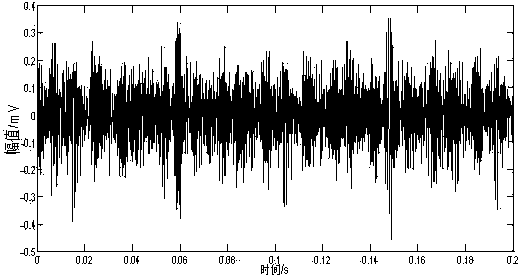
The invention relates to a fault diagnosis method for a gear of a drive system based on a vibration signal analysis. The fault diagnosis method comprises the following steps: (1) carrying out n orders of differential derivation on an original vibration signal x(t), wherein the formula is represented as the description; (2) carrying out first-order EMD (Empirical Mode Decomposition) on xn(t) to obtain a first IMF (Intrinsic Mode Functions), wherein the formula is represented as the description and rn1(t) is a residual component after the first-order EMD; (3) carrying out primary integration on IMFn1(t), wherein the formula is represented as the description; (4) carrying out the first-order EMD on b(n-1)1t to obtain a formula, wherein the formula is represented as the description and n is equal to n-1 if n-1 is more than 0; continually carrying out the steps (3) and (4); (5) if n-1 is equal to 0, carrying out DEMD (Differential Empirical Mode Decomposition) on the original vibration signal x(t) to obtain a first IMF1; and (6) enabling x2(t) to be equal to x(t)-IMF1 and carrying out the steps (1) to (5) to obtain a second IMF2; circulating the steps to obtain IMF1-IMF(i-1) after the x(t) is subjected to n orders of the DEMD, wherein xi(t) is the residual component.
Description
technical field [0001] The invention relates to a gear fault diagnosis method of a transmission system, in particular to a gear fault diagnosis method of a transmission system based on vibration signal analysis. Background technique [0002] Gears are an indispensable component for connecting and transmitting power in the transmission system of mechanical equipment. The operating conditions of gears can directly affect the working efficiency, reliability and life of the entire machine. Due to the complex structure of the entire transmission system and the harsh working environment of the gears, the failure of the gears is one of the main causes of machine failures. Therefore, the fault diagnosis of the gears is also a very important part of the fault diagnosis of the transmission system. [0003] Vibration analysis analyzes and judges early potential or existing faults by analyzing the vibration frequency, vibration amplitude, and change of vibration speed over time of rotat...
Claims
Login to View More Application Information
Patent Timeline
 IPC IPC(8): G01N29/14G01N29/46
Inventor郑小霞叶聪杰李东东符杨
OwnerSHANGHAI UNIVERSITY OF ELECTRIC POWER