Multipoint-radar collaborative imaging device based on chute position judgment and method thereof

A radar and chute technology, which is applied in the field of radar target tracking and measurement, can solve the problems of chute blocking, no solution, and the research on echo processing methods is not yet mature.

Active Publication Date: 2015-06-10
UNIV OF SCI & TECH BEIJING
View PDF5 Cites 0 Cited by
  • Summary
  • Abstract
  • Description
  • Claims
  • Application Information

AI Technical Summary

Problems solved by technology

[0004] 1. "Measurement Device for Blast Furnace Load Falling Speed" by Kobe Steel Works, Japan, the implementation method is that a single radar antenna passes through the top of the blast furnace and inserts it into the furnace obliquely and radially, without rotating scanning; it can measure the material level under the antenna The height and falling speed are similar to the mechanical material ruler, which cannot reflect the overall information of the material surface, nor can it measure the shape and settlement dynamics of the entire material surface, and it is not conducive to the current popular rotary chute fabrics. The radar signal is easily blocked and the distance is easy. Jumping, which is not conducive to 3D modeling and imaging of material surface
[0005] 2. European patent EP0017664A1 discloses a double antenna structure, which is installed at the bottom of a cylinder. The cylinder passes through the side wall of the furnace body and is inserted into the furnace along the horizontal radial direction, and the cylinder is rotated so that the antenna beam forms a one-dimensional diameter in the furnace. Directional scanning; it does not have the ability to measure the shape of the entire material surface, and the device is relatively complicated, the measurement time is too long, and maintenance is difficult
However, its imaging has higher requirements on the accuracy of the six-point radar, and it does not propose a solution to the blocking problem of the chute
[0008] From the above situation, it can be seen that modern material level detection methods can be roughly divided into three methods: single-point radar fixed-point irradiation, single-point radar two-dimensional scanning irradiation, and multi-point radar fixed-point irradiation. The material surface area of ​​single-point radar fixed-point irradiation Too small, and it is easy to produce large errors by rotating two-dimensional scanning. The research on the echo processing method of oblique incidence of radar is not yet mature, and the equipment is difficult to maintain
[0009] At present, most blast furnaces adopt the method of chute rotating cloth. For multi-point array radar, if individual radar signals are blocked by the chute, the fitting image using multi-point radar measurement data will be distorted.
No one has mentioned the problem of the chute blocking radar signals, and no reasonable solution has been given in previous related inventions

Method used


Image

  • Multipoint-radar collaborative imaging device based on chute position judgment and method thereof
  • Multipoint-radar collaborative imaging device based on chute position judgment and method thereof
  • Multipoint-radar collaborative imaging device based on chute position judgment and method thereof

Examples


Embodiment Construction

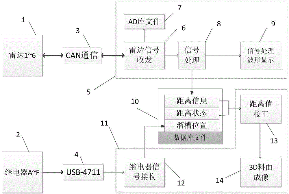
[0037] Figure 1~5 For the specific embodiment of the present invention, such as Figure 4 As shown, each radar collects AD data sequentially according to the control logic of the host computer data acquisition system, and then through such as Figure 6 The circuit shown is transmitted to the computer, and the height of the material surface is calculated by the data acquisition system, and finally the height of the material surface is processed by the imaging system for imaging.

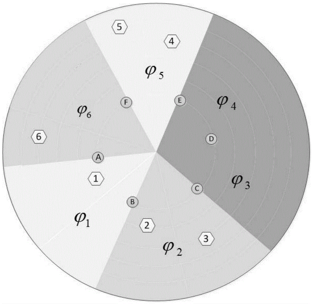
[0038] Such as figure 2 As shown, it is assumed that the radar installation numbers are 1, 2, 3, 4, 5, and 6, and 6 logic relays are installed on the 6 fan-shaped rings evenly distributed on the top of the blast furnace, assuming the serial numbers are A, B, C, D , D, F. Assume that when the chute rotates counterclockwise, relays A and B are installed in front of and behind radar 1. When the switch of relay A is triggered, it means that the chute has entered Area, mark the distance state of rada...


PUM


Abstract

The invention provides a multipoint-radar collaborative imaging device based on chute position judgment. The multipoint-radar collaborative imaging device comprises a plurality of radars arranged on a radar area on the top of a blast furnace, a plurality of relays for detecting the position of a chute, a CAN bus communication system, a data acquisition system, a database for storing distances and identification information, and an imaging system. The relays are evenly distributed in the circumferential area of the blast furnace and divide the blast furnace into a plurality of areas, all the relays detect the position of the chute in real time and judge whether measurement signals of the radars are blocked by the chute, the measurement signals are sent to an upper computer through the CAN bus communication system and received by the data acquisition system, the distances between all the radars are calculated, the identification information is acquired, then the distances and the identification information are stored into the database, data analysis and processing are carried on the distances between all the radars at last, the distances of the radars blocked by the chute are repaired, and 3D imaging is carried out. According to the multipoint-radar collaborative imaging device, the multipoint radars are used for carrying out measurement in cooperation with the multipoint relay devices, the position of the chute can be examined in real time, and the problem that the radars are blocked by the chute can be solved.

Description

technical field [0001] The invention relates to a multi-point radar cooperative imaging device and method based on chute position judgment, belonging to the field of radar target tracking and measurement. Background technique [0002] Blast furnace ironmaking works under high temperature, high pressure, and airtight conditions, and the internal working environment is extremely complex and harsh. Its internal conditions are not easy to be known to the outside world, and the distribution of the material surface is difficult to directly detect, which makes the operation of the blast furnace more experienced. It is not conducive to the optimization of ironmaking production because of its randomness and arbitrariness. Therefore, the monitoring of blast furnace charge level plays a vital role in the process of blast furnace ironmaking. The traditional material level monitoring is to collect data with a mechanical probe, and there are only 2 or 3 points, which cannot fully reflect ...

Claims


Application Information

Patent Timeline
Patent Type & Authority Patents(China)
IPC IPC(8): G01S13/89
Inventor 陈先中
Owner UNIV OF SCI & TECH BEIJING
Why Eureka
Try Eureka