Supercharge Your Innovation With Domain-Expert AI Agents!

Electrical wringing-out device for a cleaning mop

An electric mop technology, applied in applications, household appliances, carpet cleaning, etc., can solve the problems of laborious transportation and placement of containers, large volume and structure of wringing devices, etc.

Inactive Publication Date: 2013-12-25
CARL FREUDENBERG KG
View PDF6 Cites 2 Cited by
  • Summary
  • Abstract
  • Description
  • Claims
  • Application Information

AI Technical Summary

Problems solved by technology

The oval container makes the wringer device bulky, so that the container has to be transported and placed with great effort

Method used


Image

  • Electrical wringing-out device for a cleaning mop
  • Electrical wringing-out device for a cleaning mop
  • Electrical wringing-out device for a cleaning mop

Examples


Embodiment Construction

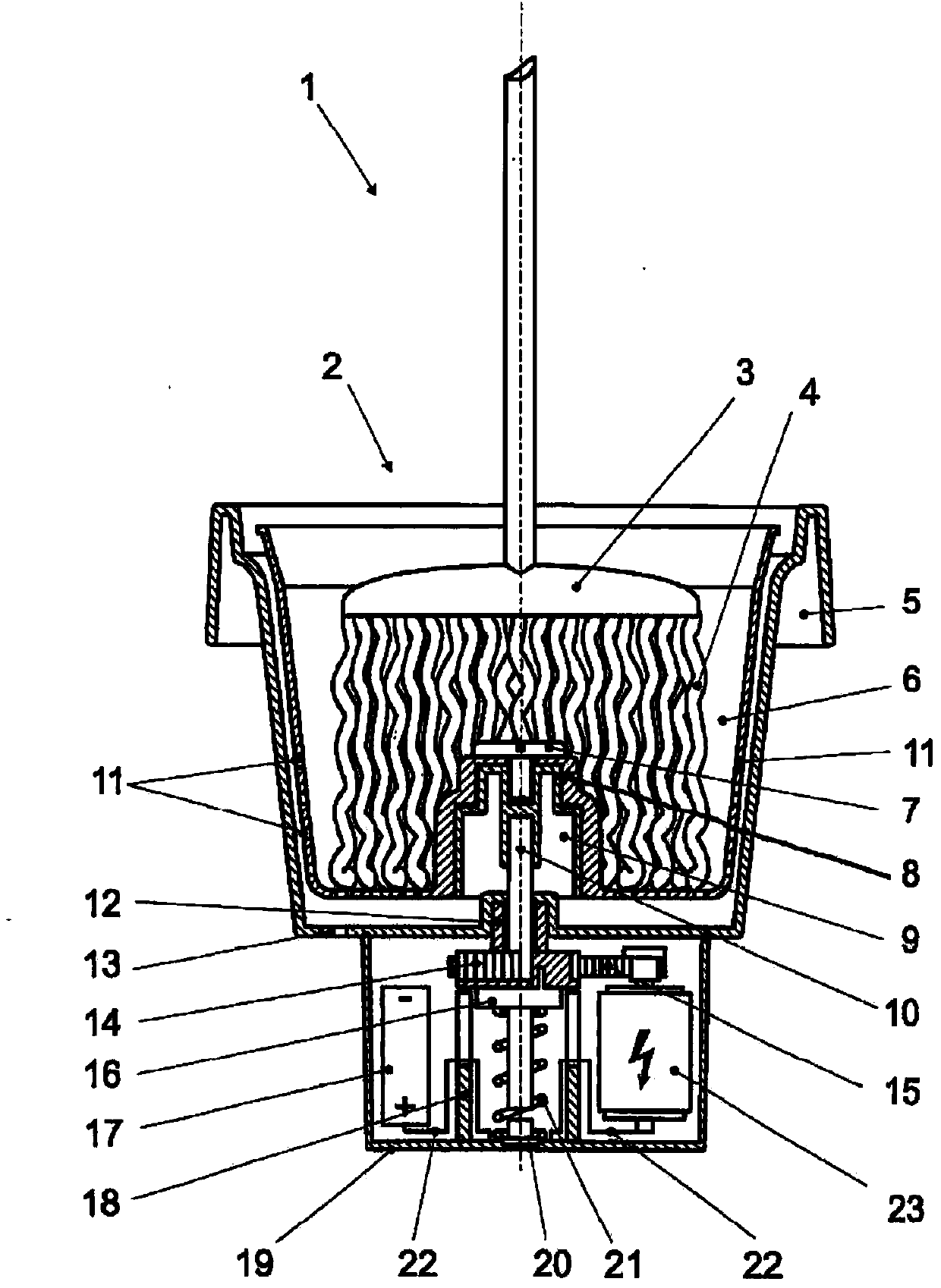
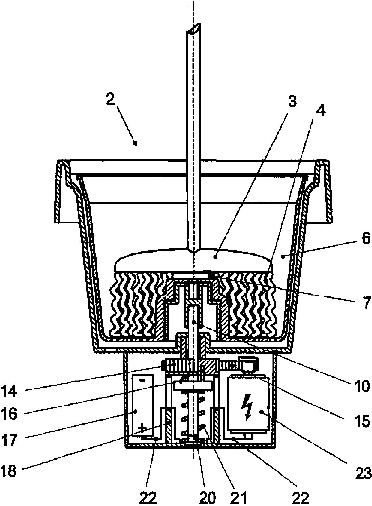
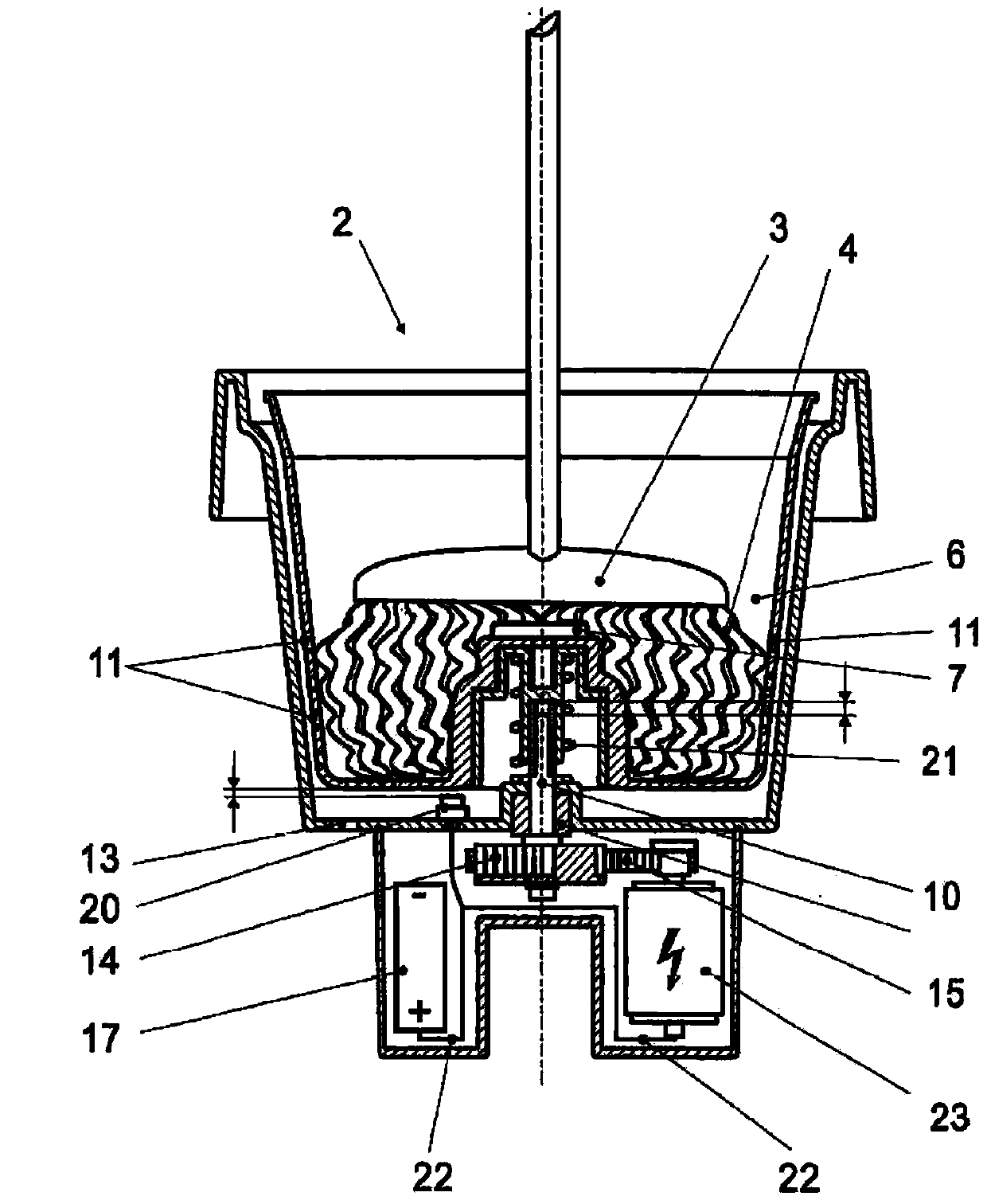
[0035] Figures 1 to 6 Each shows a module 1 with a base body 2 into which a mop head 3 with a textile mop strip 4 is inserted. The base body 2 has complementary fastening means 5 in the form of an edge, by means of which the module 1 can be detachably flanged in its entirety to existing installations (not shown). Module 1 is therefore used as a replacement part.

[0036] The dehydration basket 6 is accommodated in the base body 2 , and a connecting piece 7 is provided on the dehydration basket 6 , and the mop head 3 rests on the connecting piece 7 . Formed in the dehydration basket 6 is a receiving chamber 9 which accommodates the coupling device 8 and the drive shaft 10 . The connecting piece 7 connects the dehydration basket 6 and the coupling device 8 .

[0037] Openings 11 are formed in the dehydration basket 6 . The water that escapes from the fabric mop strip 4 when the dehydration basket 6 rotates can flow out of the dehydration basket through the openings 11 .

...


PUM


Abstract

The aim of the invention is to provide an electrical wringing-out device that can be used in different locations without problems. Said aim is achieved by a module (1) for the use in an electrical wringing-out device for a cleaning mop, comprising a main body (2) and a rotatable spinning basket (6), received in the main body (2), for holding a mop head (3), wherein openings (11) are formed in the spinning basket (6). The module is characterized in that the main body (2) is provided with a fixing means (5), by means of which the module (1) can be inserted completely or partially reversibly or non-detachably into an existing apparatus.

Description

technical field [0001] The invention relates to a module in an electric wringer for a mop. Background technique [0002] Document DE 20 2010 000 185 u1 discloses an electric wringer for mops, which has a rotatable spinner basket for receiving a mop head. [0003] The wringer can be operated without feet. Once the operator presses the mop head into the spin basket, the motor is activated which rotates the mop head causing water to escape from the mop head. [0004] Such an electric wringer known from document DE 20 2010 000 185 u1 has an oval container which holds a dehydration basket. The oval container makes the wringer device bulky, so that the container has to be transported and placed with great effort. Contents of the invention [0005] It is therefore the object of the present invention to provide an electric wringer which can be used without hindrance at different locations. [0006] The invention achieves the aforementioned object by the features of claim 1 . ...

Claims


Application Information

Patent Timeline
IPC IPC(8): A47L13/58
CPCA47L13/58
Inventor 乌维·丁格特
Owner CARL FREUDENBERG KG
Features
  • R&D
  • Intellectual Property
  • Life Sciences
  • Materials
  • Tech Scout
  • Unparalleled Data Quality
  • Higher Quality Content
  • 60% Fewer Hallucinations
Learn More