Vehicle outer mirror device

A technology for exterior rearview mirrors and vehicles, applied in vehicle parts, optical observation devices, transportation and packaging, etc., can solve problems such as deformation, and achieve the effect of improving appearance

Inactive Publication Date: 2014-01-01
KK TOKAI RIKA DENKI SEISAKUSHO +1
View PDF6 Cites 0 Cited by
  • Summary
  • Abstract
  • Description
  • Claims
  • Application Information

AI Technical Summary

Problems solved by technology

Therefore, since the shield cover is deformed by the plating process as described above, it is difficult to assemble other parts such as the shield edge and the lens with the shield cover

Method used


Image

  • Vehicle outer mirror device
  • Vehicle outer mirror device
  • Vehicle outer mirror device

Examples


Embodiment Construction

[0029] Configuration of Exemplary Embodiments of the Invention

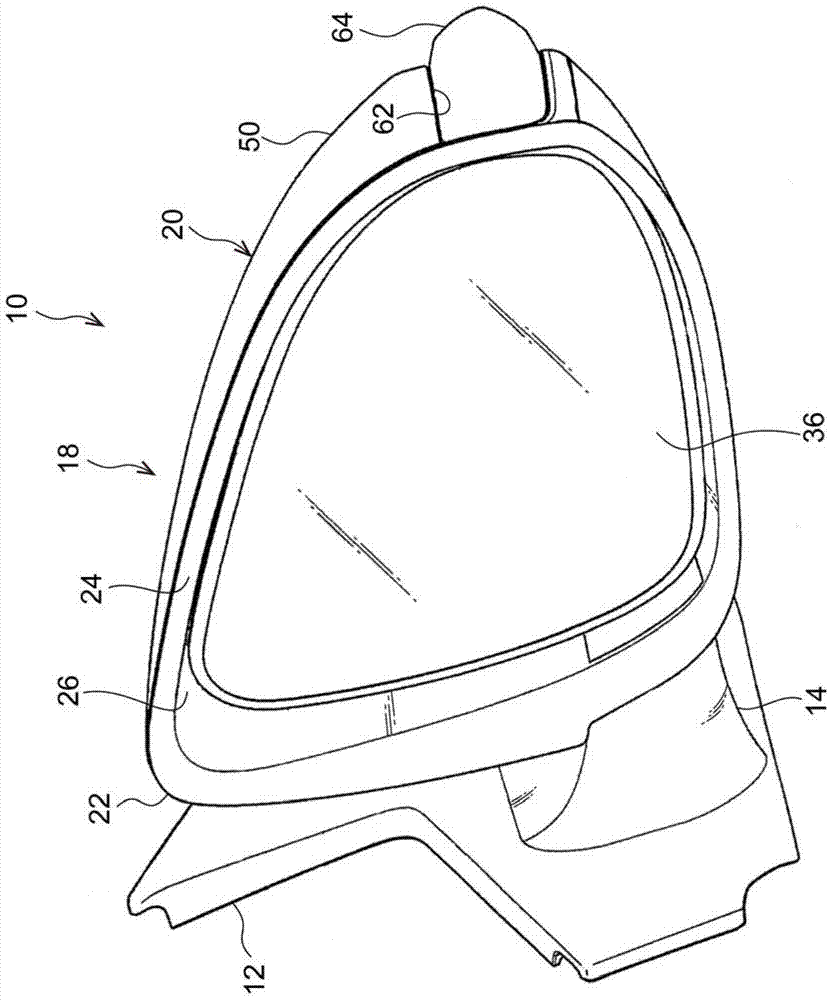
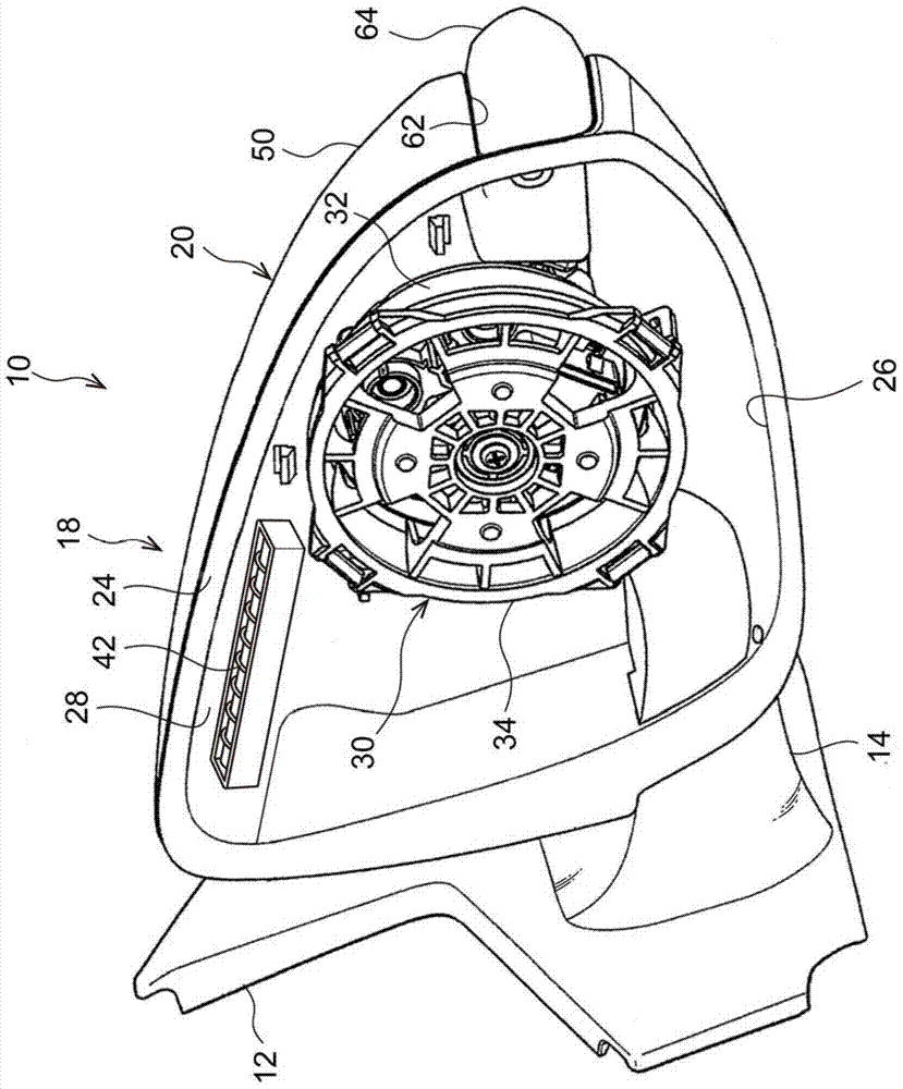
[0030] figure 2 is a perspective view showing a schematic overall configuration of a vehicle door mirror device 10 serving as a vehicle exterior mirror device according to an exemplary embodiment of the present invention, viewed from obliquely rear on the right side of the vehicle. image 3 It is a perspective view showing a main part of the vehicle door mirror device 10 as viewed obliquely from the rear on the right side of the vehicle. Figure 4 It is a rear view of the main part of the vehicle door mirror device 10 viewed from the vehicle front side.

[0031] The vehicle door mirror device 10 is provided outside (not shown in the drawings) of a vertically intermediate portion of a vehicle front side end portion of a vehicle door. Such as Figure 2 to Figure 4 Respectively shown, the vehicle door mirror device 10 is equipped with a bracket 12 serving as a supporting member. The vehicle door mirror device 1...


PUM


Abstract

A back coat, a metal thin film and a top coat are applied to an outer surface of a base member of a visor cover of a vehicle door mirror device, and in particular the metal thin film is formed by vapor deposition. The film thickness of the metal thin film can accordingly be made thinner than a case of when forming a metal film by plating, and the thickness of the metal thin film is easily managed. Accordingly, unwanted deformation of the visor cover when forming the metal thin film to the outer surface of the visor cover is not occurred, or deformation occurring in the visor cover can be suppressed.

Description

Background technique [0001] The present invention relates to a vehicle exterior mirror device, such as a door mirror or a fender mirror mounted on the exterior of a vehicle. Background technique [0002] Japanese Patent Application Laid-Open (JP-A) No. 2011-51435 (Patent Document 1) discloses a vehicle door mirror device which is an aspect of a vehicle exterior mirror device. In the vehicle door mirror device, a mirror main body (mirror) and a shield cover (referred to as "housing cover" in Patent Document 1) are attached to a bracket (referred to as "mirror base" in Patent Document 1 ), which attaches to the body of the vehicle. [0003] For example, depending on the vehicle model, the outer surface of the fender cover is colored differently. In the case where the outer surface of the shield cover is configured in a metallic color with metallic luster, plating work such as chrome plating is performed on the shield cover. [0004] In the case of forming a metal film on th...

Claims


Application Information

Patent Timeline
Patent Type & Authority Applications(China)
IPC IPC(8): B60R1/06
CPCB60R1/12H01Q1/3266B60R1/06B60R2001/1261H01Q1/3233
Inventor 滨田健宏岩月正和春田幸一齐藤贵文冈本健吾千叶忍
Owner KK TOKAI RIKA DENKI SEISAKUSHO
Why Eureka
Try Eureka