container for hydraulic circuit

A technology of hydraulic circuits and containers, which is applied in the directions of fluid pressure actuation devices, fluid pressure actuation system components, fuel supply tank devices, etc., can solve problems such as insufficient prevention

Active Publication Date: 2017-07-11
FORD GLOBAL TECH LLC
View PDF2 Cites 0 Cited by
  • Summary
  • Abstract
  • Description
  • Claims
  • Application Information

AI Technical Summary

Problems solved by technology

However, a disadvantage of such bypass valves is that they do not adequately prevent sediment or impurities that collect in the filter from entering the hydraulic circuit when the valve is open

Method used


Image

  • container for hydraulic circuit
  • container for hydraulic circuit
  • container for hydraulic circuit

Examples


Embodiment Construction

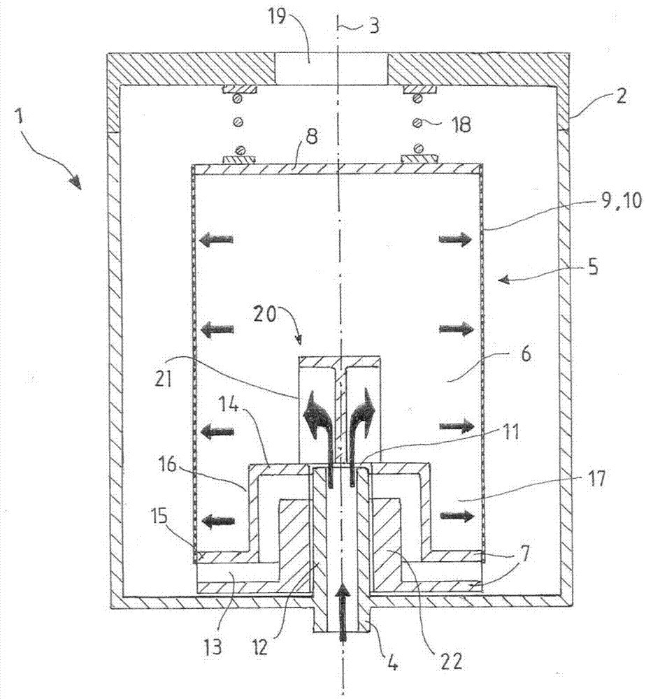
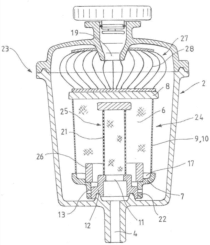
[0024] figure 1 Shows a cross-sectional side view of a first embodiment of a container 1 according to the invention for a hydraulic circuit, in particular a hydraulic oil compensation tank of a hydraulic power steering according to the invention in a first operating position. The container 1 comprises a substantially cylindrical shell 2 with a longitudinal axis 3 . Housing 2 has figure 1 Inlet 4 is shown as well as in the figure 1 Outlet not shown in , inlet 4 is used for hydraulic fluid (more specifically, hydraulic oil) from connection to container 1 but in figure 1 The hydraulic circuit, also not shown in further detail, is received into the container 1, more specifically, hydraulic fluid is received from the hydraulic circuit of the hydraulic power steering device into the container 1, and the outlet is used to discharge the hydraulic fluid to the container 1 hydraulic circuit.

[0025] From figure 1 As seen in more detail in , the container 1 comprises at least one f...


PUM


Abstract

The present invention relates to a container for a hydraulic circuit, more specifically, to a hydraulic oil compensation tank for a hydraulic power steering device, which includes a housing (2), an inlet ( 4) and outlet, at least one filter (5, 24) and bypass channel (13), the at least one filter (5, 24) is arranged between the inlet (4) and the outlet and surrounds the inner filter chamber ( 6), for separating solid constituents from a fluid flow, wherein the filter (5, 25) has an inlet opening (11) on one wall (7), which can be connected in a fluid-tight manner to the inlet (4), and a bypass passage (13) for selectively bypassing the filter (5, 24) according to a pre-determinable pressure differential between the inlet (4) and the outlet. At least one sloshing baffle (16, 26) protruding into the inner filter chamber (6) is arranged on the wall (7).

Description

technical field [0001] According to the claims, the invention relates to a container for a hydraulic circuit, more particularly to a hydraulic oil compensation tank of a hydraulic power steering device. Background technique [0002] In hydraulic circuits such as power steering for motor vehicles, it is essential for trouble-free and long-life operation that the hydraulic fluid, such as hydraulic oil, flowing through the circuit be kept free of solid components, such as Suspended particulate matter. For this purpose, known filters are used to ensure a certain quality of the hydraulic fluid. It is generally desirable to provide a filter with the smallest possible mesh width in order to be able to filter even the smallest particulate matter from the fluid flow. This type of filter is also called a fine filter. However, this can cause problems at low operating temperatures of the hydraulic circuit, for example during the initial stages of operation, since the viscosity of the...

Claims


Application Information

Patent Timeline
Patent Type & Authority Patents(China)
IPC IPC(8): F15B21/04F15B21/041
CPCB62D5/062F15B1/26F15B21/041
Inventor V·彼得曼M·G·菲古拉
Owner FORD GLOBAL TECH LLC
Why Eureka
Try Eureka