An elastic resistance mechanical brake device

A technology of mechanical braking and elastic resistance, applied in transmission, gear transmission, transmission control, etc., can solve the problems of limited adaptability, high cost, rapid oil temperature rise, etc., and achieve reliable safety performance and adaptability. Wide and explosion-proof performance

Inactive Publication Date: 2016-01-27
HUNAN UNIV OF HUMANITIES SCI & TECH
View PDF7 Cites 0 Cited by
  • Summary
  • Abstract
  • Description
  • Claims
  • Application Information

AI Technical Summary

Problems solved by technology

These devices have their own shortcomings in application; liquid viscosity technology has large starting current, rapid oil temperature rise, difficult maintenance and high cost
When the frequency conversion technology is used in high-power applications, the higher the power of the electronic components, the more expensive the cost, and the higher the power, the greater the heat. In use, the automatic governor controlled by electro-hydraulic has complex structure, high cost and limited adaptability to power.

Method used


Image

  • An elastic resistance mechanical brake device
  • An elastic resistance mechanical brake device
  • An elastic resistance mechanical brake device

Examples


Embodiment 1

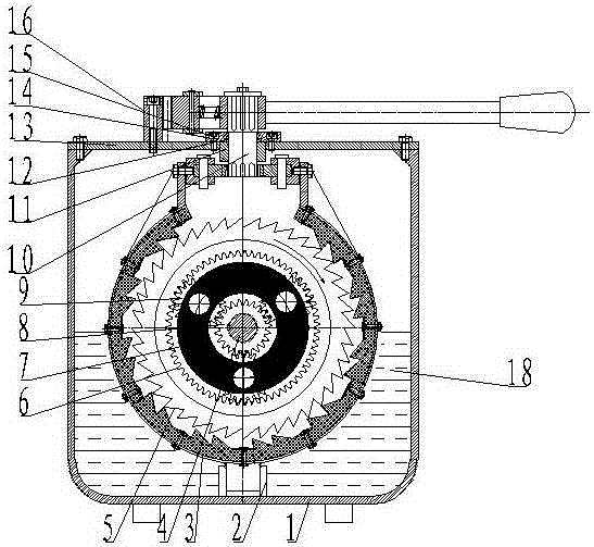
[0035] See attached figure 1 to attach Figure 8 , attached Figure 12, the elastic resistance mechanical braking device described in this embodiment includes an organic casing 1, a ratchet ring 3, a ratchet gear 5, a planetary transmission system, an operating device, and an eccentric locking device 10, wherein the planetary transmission system is assembled on In the casing 1, lubricating oil 18 is injected in the machine cavity of the casing 1; the planetary transmission system includes a power input shaft 4, a planetary ring gear 6, a planet carrier 7, a sun gear 8, and a planetary gear 9, wherein , the power input shaft 4 is assembled on one side of the planetary carrier 7, and the other side of the planetary carrier 7 is connected with the output shaft; the sun gear 8 is set on the power input shaft 4 and meshed with the planetary gear 9 installed in the planetary carrier 7, The planetary gear 9 is meshed with the planetary ring gear 6, and there are three planetary gea...

Embodiment 2

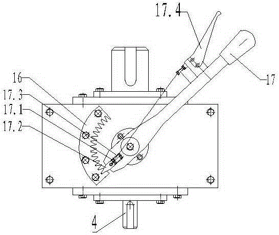
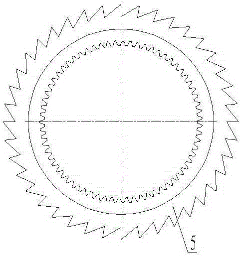
[0038] See attached Figure 9 To attach Figure 12 , the difference between this embodiment and Embodiment 1 is that the operating device is composed of a two-way hydraulic cylinder A9 and a hydraulic system A10, wherein the two-way hydraulic cylinder A9 is installed on the mounting seat, and the mounting seat is connected to both ends of the ratchet ring 3; the two-way The hydraulic cylinder A9 is connected to the hydraulic system A10 controlled by a proportional valve. The ratchet gear 5 is a compound wheel composed of outer ratchet teeth A5.1 and inner teeth A5.2, and the compound wheel is a structure designed by combining the ratchet gear and the inner ring gear. Ratchet ring 3 includes spring steel sheet A3.2, shrapnel A3.3, left locking support A3.4, right locking support A3.5, cam A3.6, third screw A3.7, installation Seat A3.8, wherein the spring steel sheet A3.2 is an arc-shaped mechanism, and a plurality of evenly distributed shrapnel A3.3 are punched on the spring ...


PUM


Abstract

The invention provides an elastic-resistance mechanical braking device which comprises a casing, a ratchet gear, a ratchet ring, a planet transmission system and a controlling device. The planet transmission system is assembled in the casing, the ratchet gear is assembled on a planet inner gear ring of the planet transmission system, a ratchet combined ring is wrapped on a gear edge of the ratchet gear and connected with the controlling device, and lubricating oil is filled in a cavity of the casing. The elastic-resistance mechanical braking device has the advantage that the mechanical braking device can generate linear resistance to a running locomotive and can realize stepless speed adjusting, soft starting, soft parking, overload protecting and multipoint driving power balancing.

Description

technical field [0001] The invention relates to the technical field of equipment braking, in particular to an elastic resistance mechanical braking device. Background technique [0002] Since the invention of the machine, human beings have been researching the brake device as a key point. The friction resistance brake device is the most primitive, but it is still the most widely used brake device. Its advantages lie in its simple structure, economy, and convenient operation and maintenance. . The disadvantage is that when friction generates heat, the power is too large, and the braking time is too long, the friction lining will be ablated and become invalid during the braking process. Then people developed a wide variety of soft start devices, such as hydraulic couplings, hydraulic torque converters, computer-controlled automatic speed control devices, variable pressure soft starters, variable frequency soft starters, liquid variable resistance soft starters, hydraulic soft...

Claims


Application Information

Patent Timeline
Patent Type & Authority Patents(China)
IPC IPC(8): F16H57/04F16H57/023F16H59/10
CPCF16H3/76F16H57/0484F16H57/10
Inventor 张海筹
Owner HUNAN UNIV OF HUMANITIES SCI & TECH
Why Eureka
Try Eureka