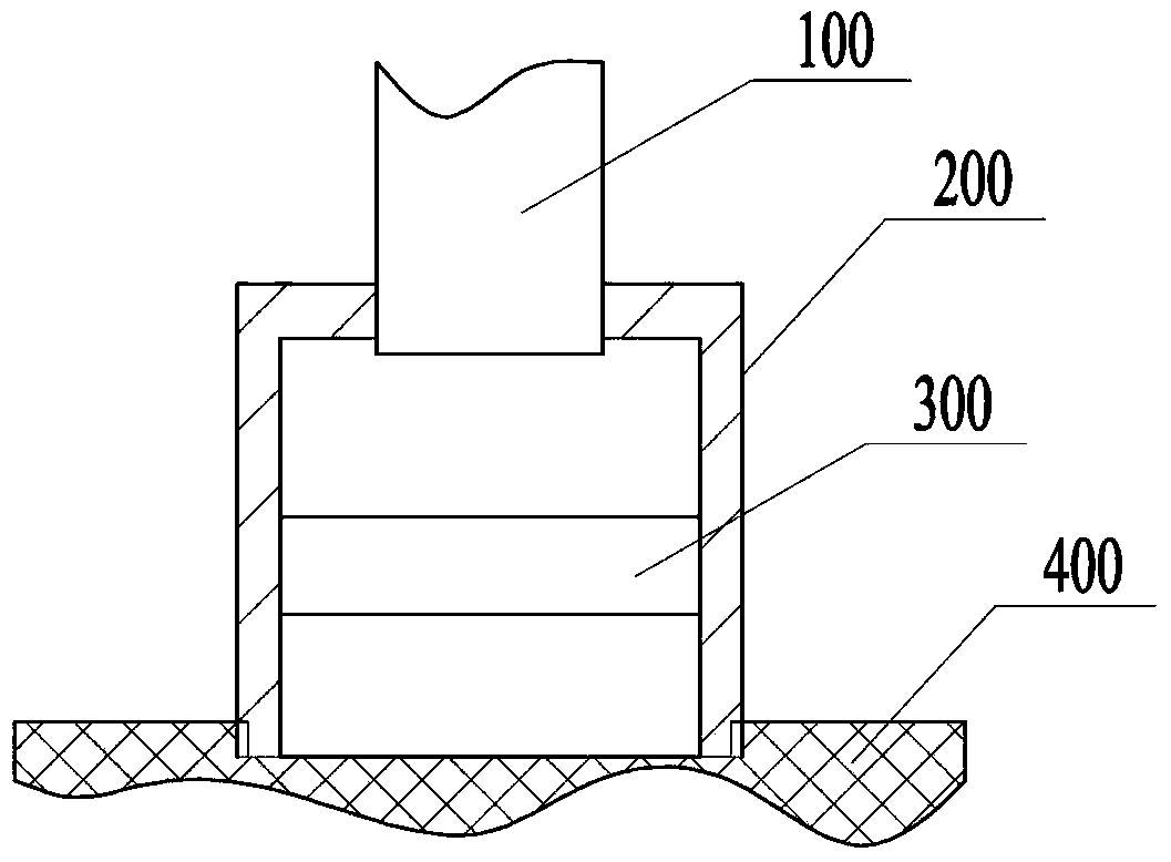
Illuminating lamp
A technology of lighting lamps and light-emitting boards, which is applied to lighting devices, lighting and heating equipment, and components of lighting devices. The effect of expanding the range of application
- Summary
- Abstract
- Description
- Claims
- Application Information
AI Technical Summary
Problems solved by technology
Method used
Image
Examples
Embodiment 1
[0041] Figure 6 A structural schematic diagram of an illuminating lamp in which the optical lens in the casing is a concave lens is shown. Such as Figure 6 As shown in , the optical lens in the casing 200 is a concave lens 310, and the concave lens 310 is located between the optical fiber 100 and the light output plate 400. The parallel light guided by the optical fiber 100 is diffused by the concave lens 310 and then emitted through the light output plate 400. , the light emitting plate used in this embodiment is a light diffusing plate. Figure 7 A schematic diagram of the optical path of the light guided by the optical fiber passing through the concave lens is shown. Such as Figure 7 As shown, the parallel light emitted by the optical fiber 100 passes through the concave lens 310 in the housing 200 and diffuses along the virtual focus of the concave lens 310, so that the light beam can be diffused. The diffused light is further diffusely transmitted through the light...
Embodiment 2
[0043] Figure 8 It shows a structural schematic diagram of an illuminating lamp in which the optical lens in the casing is a combination of a convex lens and a concave lens. Such as Figure 8 As shown in , a convex lens 320 and a concave lens 310 are installed in the housing 200, both of which are coaxial. In order to realize light diffusion, the convex lens 320 is arranged between the optical fiber 100 and the concave lens 310, the concave lens 310 is arranged between the convex lens 320 and the light output plate 400, and the concave lens 310 is located between the convex lens 320. out of focus. Figure 9 A schematic diagram of an optical path of light guided by an optical fiber passing through an optical lens system is shown. Such as Figure 9 As shown, the parallel light derived from the optical fiber converges at its focal point after passing through the convex lens 320 , and becomes divergent light after passing through the focal point. The divergent light becomes m...
Embodiment 3
[0045] Figure 10 It shows a structural schematic diagram of an illuminating lamp in which the optical lens in the casing is a combination of two concave lenses. Such as Figure 10 As shown in , two concave lenses 310 are installed in the housing 200 , the two are coaxial, and the two concave lenses 310 are both located between the optical fiber 100 and the light output plate 400 . Figure 11 A schematic diagram of an optical path of light guided by an optical fiber passing through an optical lens system is shown. Such as Figure 11 As shown, the parallel light derived from the optical fiber diffuses along the virtual focus of the concave lens after passing through the first concave lens, and the divergent light diffuses over a larger range after passing through the second concave lens. The distance between the two concave lenses can also be adjusted. By moving one of the concave lenses or moving the two concave lenses at the same time to change the relative position betwee...
PUM
 Abstract
Description
Claims
Application Information
 - R&D
- Intellectual Property
- Life Sciences
- Materials
- Tech Scout
- Unparalleled Data Quality
- Higher Quality Content
- 60% Fewer Hallucinations
Browse by: Latest US Patents, China's latest patents, Technical Efficacy Thesaurus, Application Domain, Technology Topic, Popular Technical Reports.
© 2025 PatSnap. All rights reserved.Legal|Privacy policy|Modern Slavery Act Transparency Statement|Sitemap|About US| Contact US: help@patsnap.com


