Optical fiber back-in reflection type lamp

A lighting and reflective technology, applied in the direction of lighting devices, lighting and heating equipment, parts of lighting devices, etc., can solve the problems of narrow lighting range, uncoordinated elegant environment, and monotonous light emitting surface of the light source, etc., to achieve The effect of expanding the range of application

Inactive Publication Date: 2014-01-29
云南邦桥节能科技有限公司
View PDF8 Cites 0 Cited by
  • Summary
  • Abstract
  • Description
  • Claims
  • Application Information

AI Technical Summary

Problems solved by technology

[0002] In the current lighting, the light emitted by the light source needs to be exported through the optical fiber and then directly emitted through the light-emitting surface. The lighting effect is relatively simple, and the light exported by the optical fiber is a beam of light. The illumination range of the light is relatively narrow and the light is relatively strong, which is prone to glare. The light emitting surface of some light sources is relatively monotonous, which is not in harmony with the elegant environment

Method used


Image

  • Optical fiber back-in reflection type lamp
  • Optical fiber back-in reflection type lamp
  • Optical fiber back-in reflection type lamp

Examples


Embodiment 1

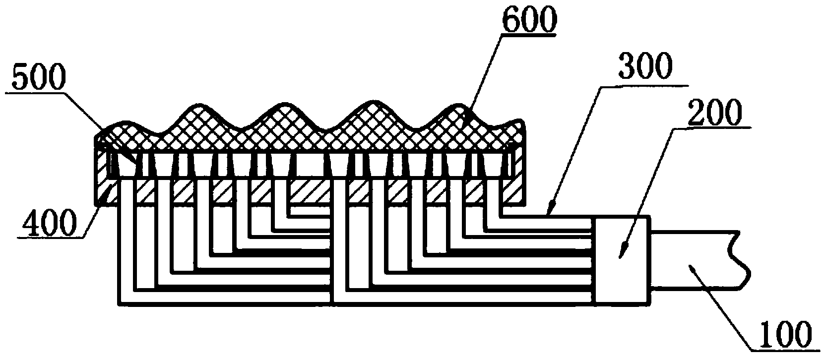
[0037] Figure 6 A structural schematic diagram of an optical system with reflective cups in the housing is shown. Such as Figure 6As shown in , the optical unit in the housing 400 is a reflective cup 510, the inner wall of the reflective cup 510 is coated with reflective material to form a reflective surface, and the whole is opaque, so as to avoid the loss of light entering the reflective cup due to transmission . Part of the sub-fiber 300 extends into the reflective cup 510, and the light output plate 600 is connected to the lower end of the reflective cup. The light output plate used in this embodiment is a light diffusion plate. When the lighting lamp is working, the light derived from the sub-fiber 300 enters the reflective cup 510, and is reflected by the inner wall of the reflective cup 510, so that the light beam can be diffused. The diffused light is further diffusely transmitted through the light-emitting plate 600 , making the emitted light soft.

Embodiment 2

[0039] Figure 7 A schematic structural view of an optical system with reflectors in the casing is shown. Such as Figure 7 As shown in , the optical unit in the housing 400 is a convex mirror 520 . The convex mirror is a kind of spherical mirror, and the convex mirror has a diverging effect on the incident light. The light emitting plate used in this embodiment is a light diffusing plate. The light exported by the sub-fiber 300 is irradiated on the convex reflector 520, and the light is reflected by the reflector 520, so that the light beam can be diffused. The diffused light is further diffusely transmitted through the light-emitting plate 600 , making the emitted light soft. A light filter is pasted on the light output plate 600 , which can transmit light of different colors as required.

Embodiment 3

[0041] Figure 8 A schematic structural diagram of an optical system of a combination of a reflector and a reflector cup is shown, wherein the reflector is a convex reflector. Such as Figure 8 As shown in , a part of the light exported by the sub-fiber 300 enters the reflective cup 510, and the light is reflected by the inner wall of the reflective cup 510, so that the light beam can be diffused. Mirror 520, the reflected light is reflected by the convex mirror 520 located at the upper end of the casing, so that the light beam can be diffused. The diffused light is further diffusely transmitted through the light-emitting plate 600 , making the emitted light soft.


PUM


Abstract

The invention discloses an optical fiber back-in reflection type lamp which comprises a main optical fiber, an optical divider, auxiliary optical fibers, an optical system and a light outlet board. The auxiliary optical fibers are connected with the main optical fiber through the optical divider, the optical system comprises a plurality of optical units, the optical units receive light guided by the auxiliary optical fibers and reflect the light out, the optical units are light reflection cups or light reflection mirrors, and the light outlet board is connected under the optical system. By means of matched use of the optical system and the light outlet board, different lighting requirements can be met, and the application range of the lamp is expanded.

Description

technical field [0001] The invention relates to an optical fiber back-introduction reflective lighting lamp. Background technique [0002] In the current lighting, the light emitted by the light source needs to be exported through the optical fiber and then directly emitted through the light-emitting surface. The lighting effect is relatively simple, and the light exported by the optical fiber is a beam of light. The illumination range of the light is relatively narrow and the light is relatively strong, which is prone to glare. The light emitting surface of some light sources is relatively monotonous, which is not in harmony with the elegant environment. Contents of the invention [0003] To this end, the present invention proposes a new lighting lamp that can solve at least part of the above-mentioned problems. [0004] The present invention provides an optical fiber back-reflective lighting lamp, comprising: a main optical fiber, an optical fiber splitter, a sub-fiber,...

Claims


Application Information

Patent Timeline
Patent Type & Authority Applications(China)
IPC IPC(8): F21S2/00F21V13/12F21K9/61
Inventor 杨仲奎马晋坤
Owner 云南邦桥节能科技有限公司
Why Eureka
Try Eureka