

Method and device for switching central processing unit (CPU) working modes according to application scenarios
A technology of application scenarios and working modes, applied in the communication field, can solve problems such as the inability to adjust the CPU working mode, insufficient battery life, etc., and achieve the effects of battery life, good experience, and high power consumption
Inactive Publication Date: 2014-01-22
NUBIA TECHNOLOGY CO LTD
View PDF3 Cites 10 Cited by
- Summary
- Abstract
- Description
- Claims
- Application Information
AI Technical Summary
Problems solved by technology
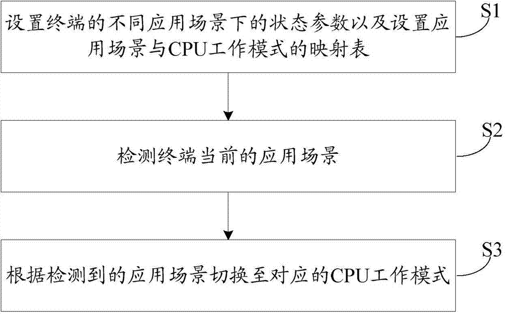
[0003] The purpose of the embodiments of the present invention is to provide a method and device for switching CPU working modes according to application scenarios, aiming to solve the problem that existing terminals cannot adjust CPU working modes according to different application scenarios, resulting in insufficient battery life
Method used
View moreImage
Smart ImageViewing Examples

Examples
Embodiment 2
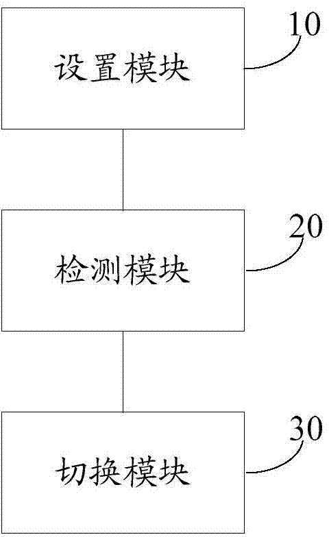
[0029] Embodiment 2 of the present invention proposes a device for switching CPU working modes according to application scenarios. The device may be the terminal itself, or a device built into or externally connected to the terminal. Such as figure 2 As shown, the device of the embodiment of the present invention includes:
[0030] The setting module 10 is configured to set state parameters of the terminal in different application scenarios; and set a mapping table between application scenarios and CPU working modes.
Login to View More PUM
 Abstract
The invention is applicable to the communication field and provides a method and a device for switching central processing unit (CPU) working modes according to application scenarios. The method includes detecting a current application scenario of a terminal; switching to a corresponding CPU working mode according to the detected application scenario and a preset mapping table of the application scenarios and the CPU working modes. By means of the method and the device, power consumption of the terminal can be reduced, and the cruising ability of batteries is improved.
Description
technical field [0001] The invention belongs to the communication field, and in particular relates to a method and a device for switching CPU working modes according to application scenarios. Background technique [0002] Battery life has become a major concern for smartphones. Nowadays, the pursuit of thinness and lightness in the structural design of smartphones makes it impossible to make the battery capacity of the device large. So how to optimize the power consumption of the system, provide the endurance of the system, and give users a good experience has become a major issue when the battery power is constant. There are many factors that affect system power consumption, including the display screen and CPU. Taking the CPU as an example, the CPU working modes generally include Interactive3, Ondemand2, Userspace4, Powersave5, Performance1, etc. Different CPU working modes have different impacts on system power consumption. In other words, the low-power mode will have a...
Claims
Login to View More Application Information
Patent Timeline
 Patent Type & Authority Applications(China)
IPC IPC(8): G06F1/32
Inventor 李超峰
Owner NUBIA TECHNOLOGY CO LTD