label equipment
A device and label technology, applied in the field of radio frequency identification, to achieve the effect of overcoming technical bottlenecks
- Summary
- Abstract
- Description
- Claims
- Application Information
AI Technical Summary
Problems solved by technology
Method used
Image
Examples
Embodiment 1
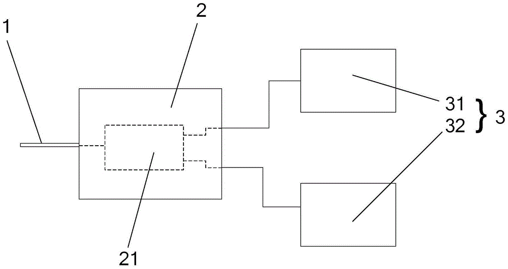
[0027] Please refer to figure 1 This embodiment provides a tag device, which includes a tag chip 2 and n antennas 3. The n antennas 3 are connected to the tag chip 2, and the tag chip 2 is made by inputting different signals to the tag chip 2. Drive one of the antennas 3 to work.
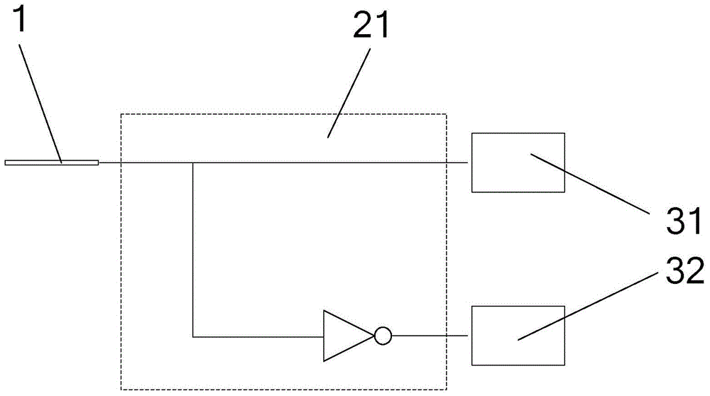
[0028] The label device also includes log 2 n pins 1, different signals are input to the tag chip 2 through the pin 1, the tag chip 2 includes a selection circuit 21, the selection circuit 21 and log 2 The n pins 1 are connected, and the selection circuit selects and drives the antenna according to the input signal of the pin 1, where n is an exponential multiple of 2. For example, when the number of antennas is 8, the number of pins is 3.
[0029] The signal input to each pin 1 includes a high-level signal when the power is on and a low-level signal when the power is off. 2 Each of the n pins 1 selects one signal for input, thereby generating n kinds of signal permutations and combinations, and the perm...
Embodiment 2
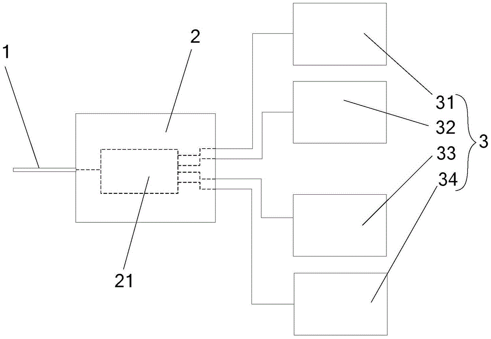
[0035] In this example, please refer to image 3 , The number of the antennas n is 4, the number of the pins is 2, which are the first pin 11 and the second pin 12;
[0036] Please refer to Figure 4 Regarding the driving of the first antenna 31, the input terminal of an AND circuit is connected to the first pin 11 and the second pin 12 at the same time, and the output terminal is connected to the first antenna 31. When the When both the first pin 11 and the second pin 12 input a high-level signal when the power is turned on, the first antenna 31 is driven to work;
[0037] Regarding the driving of the second antenna 32, an input terminal of a NOT circuit is connected to the first pin 11, and an input terminal of an AND circuit is simultaneously connected to the output terminal of the NOT circuit and the second pin 12. The output terminal of the gate circuit is connected to the second antenna 31. When the first pin 11 inputs a low level signal when the power is off, and the second ...
Embodiment 3
[0042] Please refer to Figure 5 This embodiment is different from the previous two embodiments in that it does not use the pin 1 and the selection circuit 21. The tag device includes a tag chip 2 and n antennas 3, and the n antennas 3 are connected to the tag chip 2. By inputting different signals to the tag chip 2, the tag chip 2 drives one of the antennas 3 to work. The label device also includes a micro-control unit 4, which is connected to the label chip 2, and is programmed by the micro-control unit 4 to input different signals to the label chip 2 so that the label The chip 2 drives one of the antennas 3 to work, and the programming means can be obtained according to the common sense and logical reasoning of single-chip programming, so this embodiment does not need to be illustrated.
[0043] The tag chip 2 is provided with a register 22 that is not maintained after power-off. The register 22 prestores a state data for driving one of the antennas 3 to work. When the tag chi...
PUM
 Abstract
Description
Claims
Application Information
 - R&D
- Intellectual Property
- Life Sciences
- Materials
- Tech Scout
- Unparalleled Data Quality
- Higher Quality Content
- 60% Fewer Hallucinations
Browse by: Latest US Patents, China's latest patents, Technical Efficacy Thesaurus, Application Domain, Technology Topic, Popular Technical Reports.
© 2025 PatSnap. All rights reserved.Legal|Privacy policy|Modern Slavery Act Transparency Statement|Sitemap|About US| Contact US: help@patsnap.com


