Shedding equipment for looms

A shed and equipment technology, applied in the field of shed forming equipment, can solve the problems of increased energy consumption and achieve the effect of reduced energy consumption

Active Publication Date: 2016-09-07
N V MICHEL VAN DE WIELE
View PDF5 Cites 0 Cited by
  • Summary
  • Abstract
  • Description
  • Claims
  • Application Information

AI Technical Summary

Problems solved by technology

Higher magnetic flux can be generated for improved reliability, but this in turn results in increased power consumption

Method used


Image

  • Shedding equipment for looms
  • Shedding equipment for looms
  • Shedding equipment for looms

Examples


Embodiment Construction

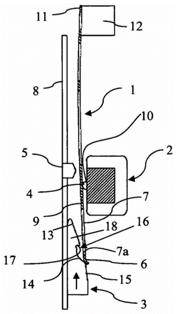
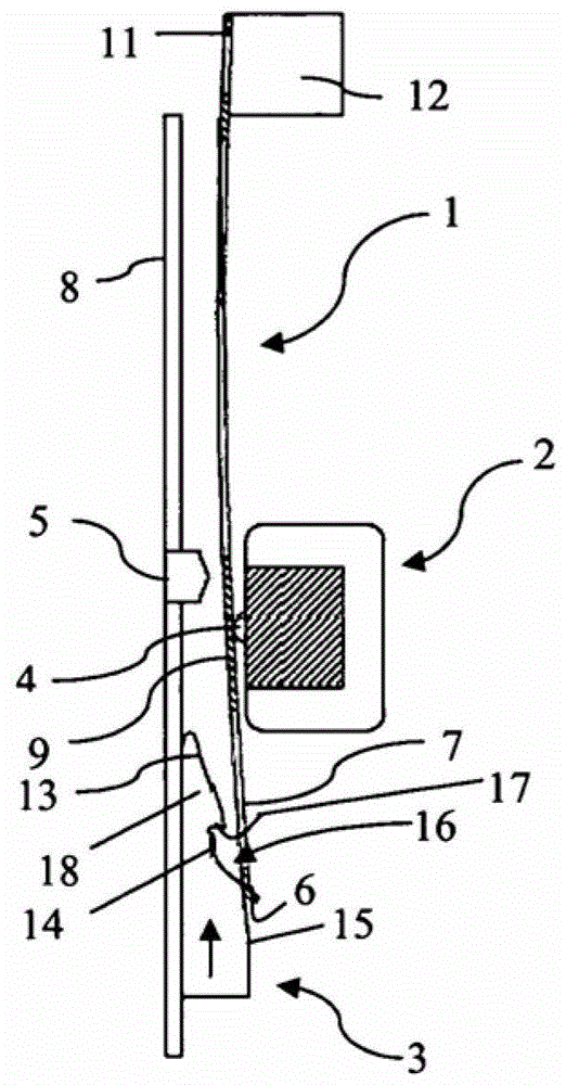
[0111] exist Figures 1 to 19 In the arrangement shown schematically, the selection element (1) is designed in each case as a thin strip of flexible and elastically deformable material, the upper end (11) of the selection element being attached to the shedding device fixed part (12). The attached selector element (1) extends at a small angle to the left in the vertical direction (V). There is a fixed support element (5) on the left hand side of the needle selection element. If no force is applied to the selector element (1), the selector element (1) rests against the fixed support element (5) due to its elasticity, as a result, it is subjected to a slight prestress which counteracts the Warp to the right. The support element (5) ensures the position of the needle selection element (1) relative to other components, in particular relative to the presentation device.

[0112] The needle selector element (1) has at its free end an end (6) bent to the right at an obtuse angle a...


PUM


Abstract

The invention relates to a shedding device comprising elastically deformable needle selection elements (1), (28a)-(28f), which can be placed in an undeformed position or a deformed position; an electromagnetic needle selector (2) , which can be actuated to place or hold each needle selection element (1) in one of said positions in successive weft insertion cycles; The needle selection elements (1) are mechanically deformed in the direction of the needle selector (2) into a presentation position in which they are kept at a distance from the needle selector (2) by a stop (4). The invention also relates to a method for such positioning of a needle selection element of a shedding device.

Description

technical field [0001] The present invention relates to a shedding apparatus for a loom, comprising: a plurality of elastically deformable selector elements, each selector element can be selectively placed in an undeformed position or a deformed position to determine at least one warp yarn position; a number of electromagnetic needle selectors, capable of being actuated to place or maintain each needle selection element in one of said positions in a continuous weft insertion cycle, so that the warp yarns are positioned according to a predetermined weaving pattern; presenting means ), designed to exert a mechanical force on a number of undeformed selector elements in each weft insertion cycle so that said selector elements deform in the direction of the associated selector. Background technique [0002] When fabric is woven on a loom, the warp yarns are positioned relative to the weft yarns at the height at which they are introduced in each weft insertion cycle during success...

Claims


Application Information

Patent Timeline
Patent Type & Authority Patents(China)
IPC IPC(8): D03C3/20
CPCD03C3/20D03C3/00D03C1/005D03C13/00A61M2205/33A61M2205/3372A61M2205/366
Inventor J·A·格雷厄姆M·西奥巴尔德B·范德吉奥哥特F·德梅茨
Owner N V MICHEL VAN DE WIELE
Why Eureka
Try Eureka