Eureka AIR delivers breakthrough ideas for toughest innovation challenges, trusted by R&D personnel around the world.

Pipe wall biofilm growth simulation reactor

A reactor and biofilm technology, applied in the field of simulated reactors, can solve the problems of small reference, small surface area, unfavorable long-term continuous and stable operation of the simulated system, etc., and achieve the effect of simple operation

Inactive Publication Date: 2014-02-12
TONGJI UNIV
View PDF3 Cites 6 Cited by
  • Summary
  • Abstract
  • Description
  • Claims
  • Application Information

AI Technical Summary

Problems solved by technology

However, the surface area for the biofilm to attach to the two pipeline simulated reactors is small, and it is inconvenient to sample the biofilm on the wall of the non-circulatory simulated pipeline. At the same time, the sampling process is destructive to the tube wall, which is not conducive to the long-term continuous and stable operation of the simulated system.
However, the hydraulic conditions and nutrient status of the water body in the circulation simulation pipeline are quite different from the actual pipeline conditions, and the reference is less

Method used


Image

  • Pipe wall biofilm growth simulation reactor

Examples


Embodiment 1

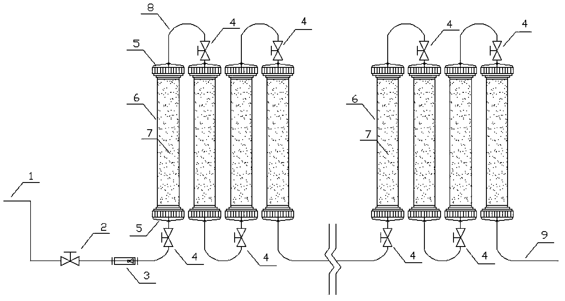
[0026] A kind of pipe wall biofilm growth simulation reactor, the structure is as follows figure 1 Shown, comprise water inlet pipe 1, water outlet pipe 9 and reactor body, between water inlet pipe 1 and water outlet pipe 9, connect a plurality of reactor bodies connected in series, reactor body is made up of water delivery pipe section 6, threaded cap 5 and filler 7 The two ends of the water delivery pipe section 6 are provided with detachable threaded ports, and the threaded caps 5 are connected through the threaded ports, and the filler 7 is arranged inside the water delivery pipe section 6;

[0027] Water enters from the water inlet pipe 1, penetrates each reactor body in turn, flows out from the water outlet pipe 9, takes out the filler 7 in the water delivery pipe section 6, collects the biofilm on the filler 7, and collects water samples at the outlet pipe 9 for analysis , the simulated pipeline is ideally a plug-flow reactor, and the hydraulic and water quality conditi...

Embodiment 2

[0035] A kind of pipe wall biofilm growth simulation reactor, the structure is as follows figure 1 shown. The water inlet pipe 1 is connected to the water tap, and the water inlet flow regulating valve 2 and the flow meter 3 are installed on the water inlet pipe. The water inlet pipe is connected with the water delivery pipe section 6 through the threaded cap 5, and a water inlet valve 4 is installed at the water inlet end of the pipe section. The inside of the water delivery pipe section 6 is filled with a filler 7, and the other end is tightly sealed by a threaded cap 5. Two adjacent threaded caps 5 are connected by connecting elbow 8 and can be made into one. Then connect the next pipe section by the threaded cap 5, and the inside of the pipe section is also loaded with the same amount of plastic packing, and so on to assemble. The last section of the pipe section is connected with the water outlet pipe 9 through the threaded cap 5, and the water outlet pipe 9 can be int...


PUM

PropertyMeasurementUnit
diameteraaaaaaaaaa
lengthaaaaaaaaaa
diameteraaaaaaaaaa

Abstract

The invention relates to a pipe wall biofilm growth simulation reactor, which comprises a water inlet pipe, a water outlet pipe and reactor bodies. The water inlet pipe and the water outlet pipe are connected by a plurality of reactor bodies in series connection. Each reactor body is composed of water pipe sections, threaded caps and fillers. Both ends of the water pipes are provided with dismountable threaded ports, and are connected to the threaded caps through the threaded ports. The fillers are disposed in the water pipes. Water enters from the water inlet pipe, penetrates each reactor body in order, and flows out from the water outlet pipe. The fillers in the water pipe sections are taken out, the biofilms on the fillers are collected, and a water sample is collected at the water outlet pipe to perform analysis. Compared with the prior art, the pipe wall biofilm growth simulation reactor provided by the invention truly simulates the hydraulic conditions and nutritional status of actual pipes, at the same time increases the biofilm attachment area, so that operation of the biofilm collection process can be simple, and no destructive effect is generated to the pipe walls.

Description

technical field [0001] The invention relates to a simulated reactor, in particular to a simulated reactor for the growth of pipe wall biofilm. Background technique [0002] At present, there are two designs of known water supply pipeline simulation systems: non-circulatory design and circular design. The non-circulatory design system is essentially a plug-flow reactor, and the biodegradable organic matter is continuously consumed by microorganisms as the pipeline distance increases. The cycle design system can be idealized as complete mixing inside the continuous stirring reactor system, and the effluent water quality is basically the same as the internal water quality conditions of the system. However, the surface area for the biofilm to attach to the two pipeline simulated reactors is small, and it is inconvenient to sample the biofilm on the wall of the non-circulatory simulated pipeline. At the same time, the sampling process is destructive to the tube wall, which is no...

Claims


Application Information

Patent Timeline
Patent Type & Authority Applications(China)
IPC IPC(8): C12M1/00
CPCC12M23/06C12M23/58C12M25/06
Inventor 李伟英陆辉吕田天郭金涛李平波沈程程
Owner TONGJI UNIV
Why Eureka
Eureka Blog
Learn More