Die for Slitting and Punching Lamination Forming for Hinged Stator

A forming mold, hinged technology, applied in the field of motor stator manufacturing and motor manufacturing, to achieve the effect of convenient opening or closing action, simple structure of punch telescopic mechanism, and low cost

Active Publication Date: 2015-11-18
闳深精密模具(常州)有限公司
View PDF7 Cites 0 Cited by
  • Summary
  • Abstract
  • Description
  • Claims
  • Application Information

AI Technical Summary

Problems solved by technology

Since most of the motor stator cores assembled in blocks use flying fork winding machines to wind the coils, the slots are formed by splicing two adjacent stator tooth blocks, so there is no problem of wire nozzles passing through the stator slots, and The slot width of the stator is made as narrow as possible or even a closed slot, which eliminates the above problems, but there are also: the structure is not tightly matched, it is easy to leak magnetic flux, the splicing magnetic circuit between the blocks is disconnected, and the iron loss will increase. The assembly process is complicated, the welding process is cumbersome, and special tooling is required for assembly. When assembling, the blocks are easily misaligned, the top and bottom are inconsistent, there are many thread ends, the production efficiency is low, and the motor energy consumption is high.

Method used


Image

  • Die for Slitting and Punching Lamination Forming for Hinged Stator
  • Die for Slitting and Punching Lamination Forming for Hinged Stator
  • Die for Slitting and Punching Lamination Forming for Hinged Stator

Examples


Embodiment 1

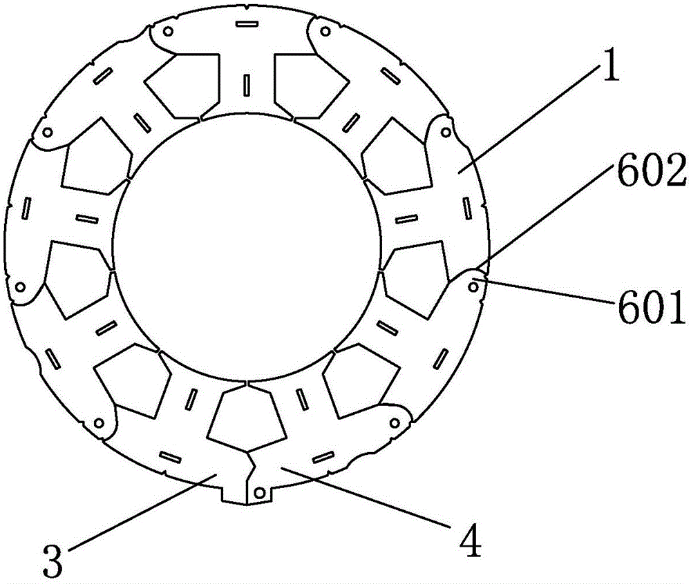
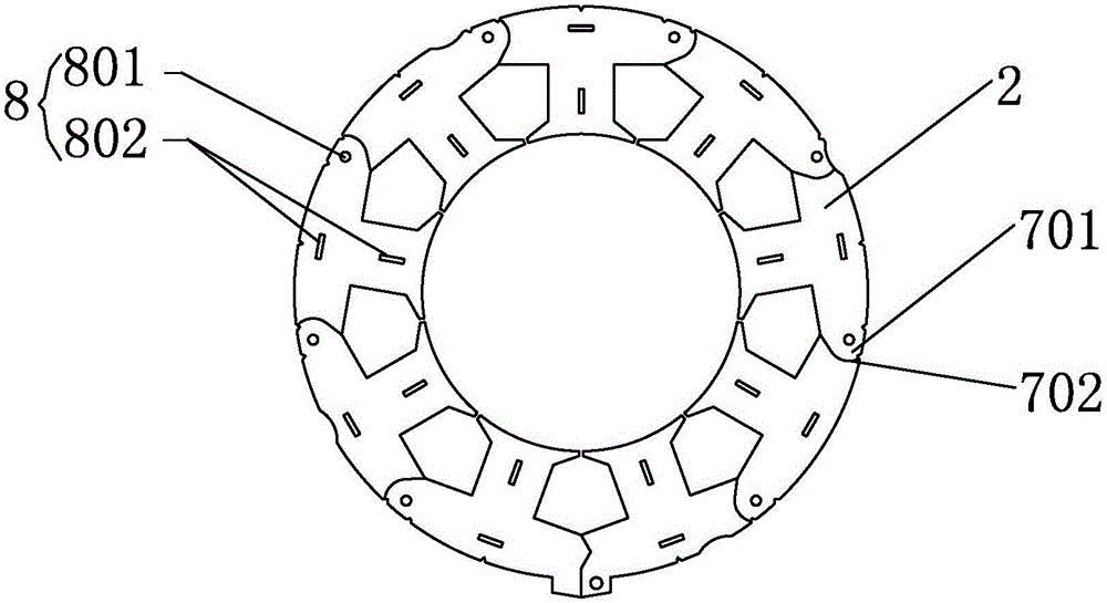
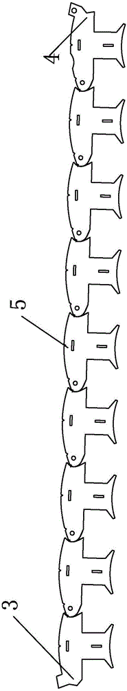
[0029] See Figure 1 to Figure 5 A hinged stator is shown, which includes: a main body 5 composed of several fan-shaped blocks suitable for hinged head to tail sequentially, and a first fan-shaped sub-block 3 and a tail fan-shaped sub-block 4 hinged at both ends of the main body , each fan-shaped block is composed of several left-handed fan-shaped sub-blocks 101 and right-handed fan-shaped sub-blocks 201 alternately stacked up and down. When the first fan-shaped sub-block 3 is connected to the outer end of the tail fan-shaped sub-block 4, the The hinged stator is a closed loop; the joints at the first and last ends of the fan-shaped block are respectively formed by the joints of the corresponding left-handed fan-shaped sub-block 101 and right-handed fan-shaped sub-block 201; the left-handed and right-handed fan-shaped sub-blocks The blocks are respectively formed by superimposing corresponding number of left-handed fan-shaped punches 1 and right-handed fan-shaped punches 2; ...

Embodiment 2

[0057] See Figure 1 to Figure 11 As shown, the manufacturing method of the hinged stator based on the first embodiment, the die process involved in the manufacturing method includes:

[0058] Stamping process S001: Punching and guiding the guiding nail or guiding pin;

[0059] Die stamping process S002: Punching the shape process gap;

[0060] Stamping process S003: groove shape;

[0061] Stamping process S004: vacancy;

[0062] Stamping process S005: punching the arc-shaped cutout 602 of the left hinge 601;

[0063] Stamping process S006: leveling;

[0064] Stamping process S007: punching the arc-shaped cutout 702 of the right hinge 701;

[0065] Stamping process S008: leveling;

[0066] Stamping process S009: vacancy;

[0067] Stamping process S010: measurement;

[0068] Stamping process S011: punching the inner hole;

[0069] Stamping process S012: Punching and riveting points;

[0070] Stamping process S013: vacancy;

[0071]Stamping...


PUM


Abstract

The invention relates to a slit punching sheet overlying and forming die suitable for hinge type stators. The slit punching sheet overlying and forming die is a progressive die and comprises an upper die base and a lower die base. The upper die base comprises a left punching male die assembly, a right punching male die assembly, an overlying and riveting male die assembly and an appearance blanking male die. The lower die base comprises a left punching female die assembly corresponding to the left punching male die assembly, a right punching female die assembly corresponding to the right punching male die assembly, an overlying and riveting female die assembly corresponding to the overlying and riveting male die assembly, and an appearance blanking female die corresponding to the appearance blanking male die. By means of the slit punching sheet overlying and forming die, the hinge type stators are assembled into a finished hinge type stator from scattered fan-shaped punching sheets, and the slit punching sheet overlying and forming die has the advantages of being high in production efficiency and low in cost.

Description

technical field [0001] The invention relates to the field of motor manufacturing, in particular to the technical field of motor stator manufacturing. Background technique [0002] The existing motor stator iron core is formed by stacking punched sheets. The punching sheet is a one-piece ring structure. The inner winding machine is used to wind the wire on the stator core installed with insulating medium. The nozzle of the inner winding machine can only be wound through the slot on the stator core. Therefore, the width of the slot must be greater than the width of the nozzle, that is, the notch must be wider. However, the wide slot of the stator of the motor will cause the rotor of the permanent magnet motor to generate a huge cogging torque when it rotates, which restricts the application of the motor in the field of high-precision control. At the same time, when the wire nozzle reciprocates in the winding process, there will be skeletons, and the wire nozzle is easy to b...

Claims


Application Information

Patent Timeline
Patent Type & Authority Patents(China)
IPC IPC(8): B21D37/10
Inventor 巢波
Owner 闳深精密模具(常州)有限公司
Why Eureka
Try Eureka