gear locking device

A locking device and gear technology, applied in the mechanical field, can solve the problems of low cost, high reliability, difficult and simple structure of the gear locking device, and achieve the effects of low production cost, high reliability and simple structure

Active Publication Date: 2016-05-04
四川川龙拖拉机制造有限公司
View PDF10 Cites 0 Cited by
  • Summary
  • Abstract
  • Description
  • Claims
  • Application Information

AI Technical Summary

Problems solved by technology

[0003] The purpose of the present invention is to provide a gear locking device to solve the problem that the existing gear locking device is difficult to meet the requirements of simple structure, high reliability and low cost

Method used


Image

  • gear locking device
  • gear locking device
  • gear locking device

Examples


Embodiment Construction

[0011] The present invention will be described in further detail below through specific implementation examples and in conjunction with the accompanying drawings.

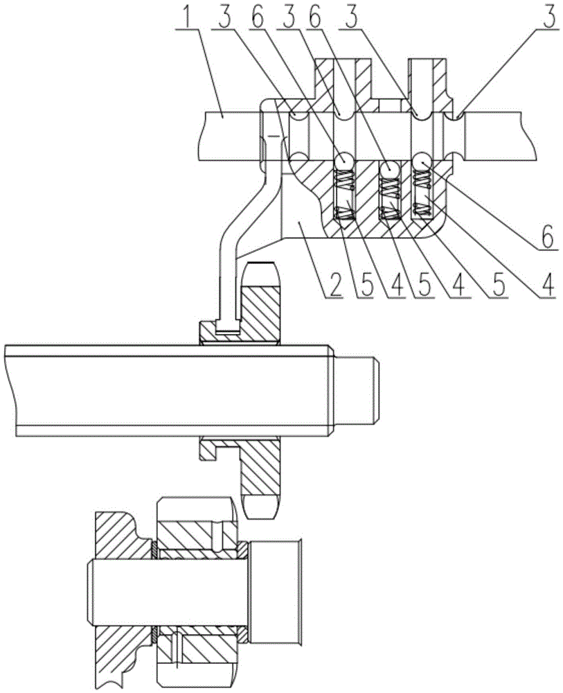
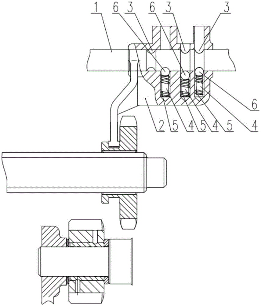
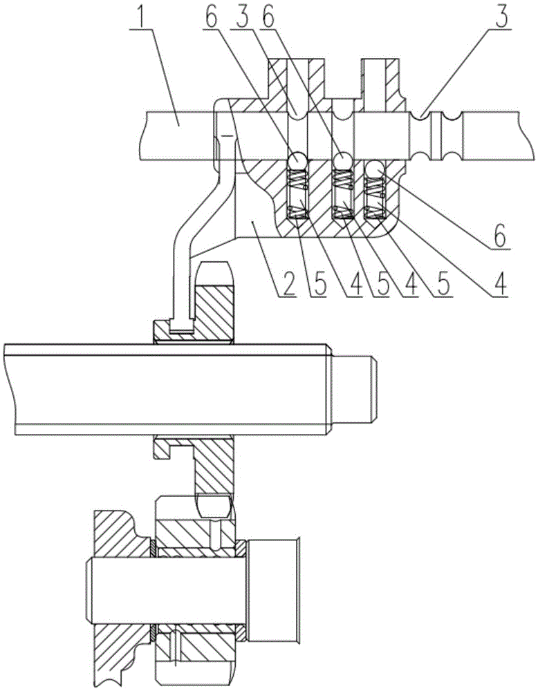
[0012] Figure 1 to Figure 3 It shows the gear locking device provided by the embodiment of the present invention, which includes a shift fork body 2 and a shift fork shaft 1 that passes through the shift fork body 2 and movably cooperates with the shift fork body 2. The shift fork shaft 1 is provided with a card slot 3, A blind hole 4 is provided on the side of the shift fork body 2 close to the card slot 3, a spring 5 and a lock ball 6 placed on the spring 5 are arranged in the blind hole 4, there are four card slots 3, and three blind holes 4 , the slot 3 and the blind hole 4 are arranged along the axial direction of the fork shaft 1, and the two blind holes 4 correspond to the two slots 3 respectively. The locking ball 6 is a steel ball, and the draw-in groove 3 is an annular groove. The gear locking device o...


PUM


Abstract

The invention belongs to the technical field of machinery and discloses a gear locking device which comprises a shifting fork body and a shifting fork shaft penetrating the shifting fork body and movably matched with the same. The shifting fork shaft is provided with at least four clamping grooves, three blind holes are arranged on one side, close to the clamping grooves of the shifting fork body, and a spring and a lock ball disposed on the spring are arranged in each blind hole. The gear locking device is characterized in that the clamping grooves and the blind holes are all arranged along the axial direction of the shifting fork shaft, and two of the blind holes correspond to two of the clamping grooves respectively. The two blind holes corresponding to the clamping grooves on the shifting fork shaft are arranged on the shifting fork body, so that the shifting fork body is enabled to be clamped in the corresponding clamping grooves of the shifting fork shaft, two lock balls are under the action of spring force no matter the shifting fork body is in an empty gear or any gear, and effect of gear locking is realized. The gear locking device is high in reliability, simple in structure and low in manufacturing cost.

Description

technical field [0001] The invention relates to the field of mechanical technology, in particular to a gear locking device. Background technique [0002] The gear locking device of a car is mainly used for self-locking of the gear to prevent disengagement. The gear locking device of most cars adopts a self-locking method of a spring and a locking ball, and the locking ball is usually a steel ball. Among them, most of the small four-wheel tractors are equipped with a set of springs and steel balls in the shift fork body. When shifting gears, the shift fork body moves, and the steel ball is inserted into the slot of the shift fork shaft by the force of the spring, thereby realizing locking. The structure is simple . However, it will be worn out after a period of use, which is easy to cause disengagement, and the reliability of gear locking is low; there is also a way of linkage with the clutch pedal, but it is necessary to change the structure of the gearbox housing and incre...

Claims


Application Information

Patent Timeline
Patent Type & Authority Patents(China)
IPC IPC(8): F16H63/34F16H63/32
CPCF16H63/32F16H63/34F16H2063/321
Inventor 陈志李凤咏毛峰谢林俐杨丽王林廖传建
Owner 四川川龙拖拉机制造有限公司
Why Eureka
Try Eureka