Eureka AIR delivers breakthrough ideas for toughest innovation challenges, trusted by R&D personnel around the world.

Fluid flow heat-exchanging experimental device with ball socket/ball bulge flow control structure

A flow control and fluid flow technology, which is applied in the field of fluid flow heat transfer experimental devices, can solve the problems of time-consuming and laborious, and the channels are not universal, and achieve the effect of avoiding experimental errors.

Active Publication Date: 2014-03-05
XI AN JIAOTONG UNIV
View PDF3 Cites 13 Cited by
  • Summary
  • Abstract
  • Description
  • Claims
  • Application Information

AI Technical Summary

Problems solved by technology

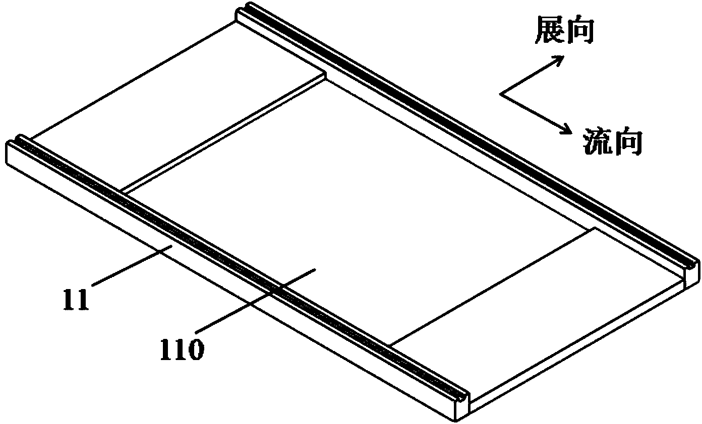
[0009] Furthermore, when designing the channels of the existing ball-and-socket / spherical-convex flow control structures, they are all integrally designed and integrally molded in a CNC machining center. The geometric parameters of the channel obtained by this method are fixed. If the geometric parameters (such as the ball and socket / span-to-convex spacing, flow-to-flow spacing, etc.) change, the entire channel must be re-processed, not only time-consuming and laborious, but also the channel is not universal

Method used


Image

  • Fluid flow heat-exchanging experimental device with ball socket/ball bulge flow control structure
  • Fluid flow heat-exchanging experimental device with ball socket/ball bulge flow control structure
  • Fluid flow heat-exchanging experimental device with ball socket/ball bulge flow control structure

Examples


Embodiment Construction

[0040] The present invention will be described in further detail below in conjunction with the accompanying drawings.

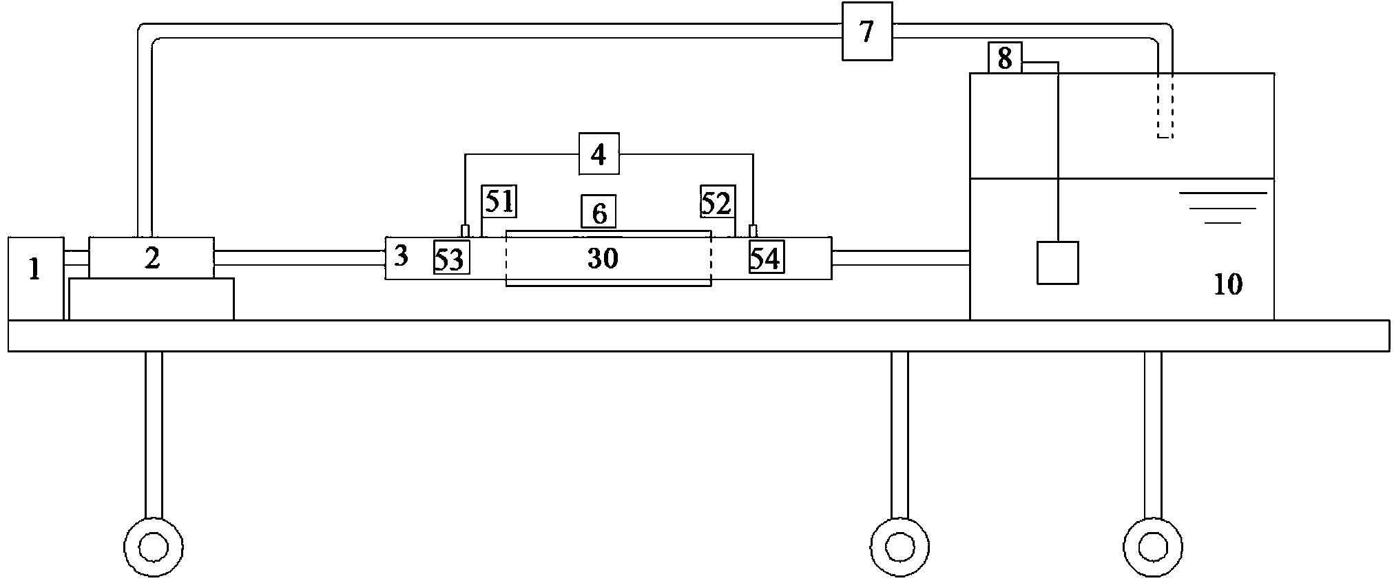
[0041] see Figure 1 to Figure 10 As shown, the fluid flow heat exchange experimental device with ball-and-socket / spherical-convex flow control structure of the present invention includes a speed-regulating motor 1, a centrifugal pump 2, a test section 3, a differential pressure transmitter 4, a thermal resistance temperature measurement system 5, Electric heating system 6 is, flow meter 7, water tank temperature control system 8 and water tank 10.

[0042] The water outlet of the water tank 10 is connected to the inlet of the test section through the channel inlet section, the outlet of the test section is connected to the inlet of the centrifugal pump 2 through the channel outlet section, and the outlet of the centrifugal pump 2 is connected to the water tank 10 through a pipeline. The channel inlet section is a round to square joint, which is used to connec...


PUM


Abstract

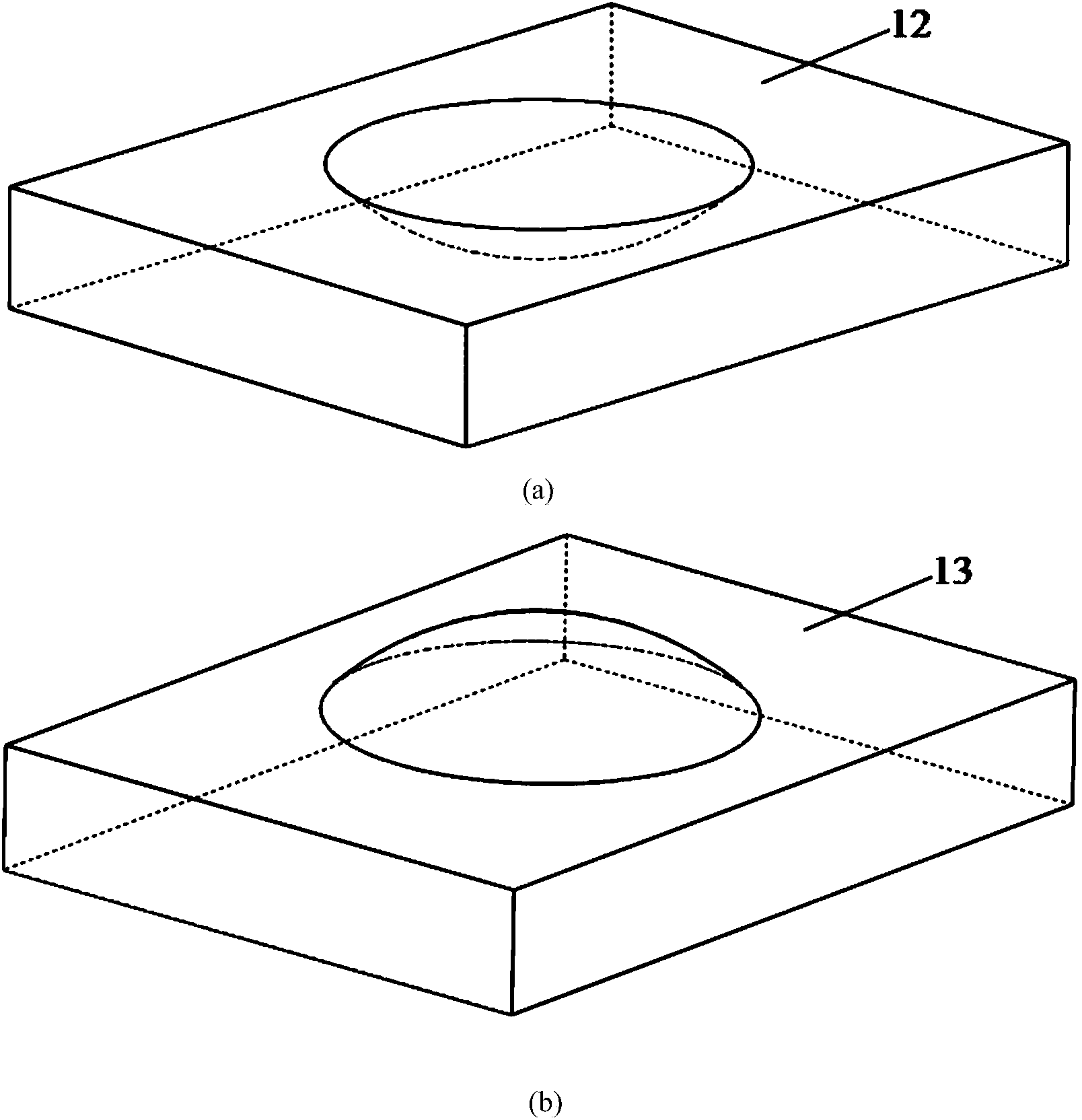
The invention discloses a fluid flow heat-exchanging experimental device with a ball socket / ball bulge flow control structure. The fluid flow heat-exchanging experimental device comprises a speed adjusting motor, a centrifugal pump, a testing section, an electric heating system, a flow meter, a water tank temperature control system and a water tank, wherein the speed adjusting motor is connected with the centrifugal pump; a water outlet of the water tank is communicated with an inlet of the testing section and an outlet of the testing section is communicated with the inlet of the centrifugal pump; the outlet of the centrifugal pump is communicated with the water tank; the testing section comprises an experimental channel upper cover plate and an experimental channel lower cover plate which are buckled with each other; a concave region is arranged in the middle of the experimental channel lower cover plate; the concave region is internally filled with a building block type ball socket / ball bulge flow control structure. According to the fluid flow heat-exchanging experimental device, a relative depth, a spanwise spacing and a streamwise spacing of a ball socket / ball bulge in a channel and the manner of combining the ball socket with the ball bulge are changed by replacing the ball socket / ball bulge, a spanwise filling block, a streamwise filling block and the like; a whole molding design method of the testing channel is improved by the design; building block type blocked structural design is adopted and the change of geometrical parameters of the channel can be finished conveniently and rapidly in a time-saving and labor-saving manner.

Description

【Technical field】 [0001] The invention relates to the technical field of flow heat exchange, in particular to a fluid flow heat exchange experimental device. 【Background technique】 [0002] Energy and mass transfer processes are involved in the fields of national defense, biomedicine, aerospace, and electronics, among which energy-efficient and compact heat exchange equipment plays a key role. With the rapid development of science and technology and the increasingly prominent energy problems, the load and heat exchange intensity of heat exchange equipment are gradually increasing. Therefore, higher requirements are put forward for the heat exchange efficiency of the heat exchange system. More and more attention has been paid by the world and engineering circles. [0003] The ball socket and the ball convex are a kind of spherical pits and protrusions arranged according to certain rules on the wall surface, and are a passive control structure. Scholars at home and abroad ha...

Claims


Application Information

Patent Timeline
Patent Type & Authority Applications(China)
IPC IPC(8): G01N25/20
Inventor 谢永慧李平张荻
Owner XI AN JIAOTONG UNIV
Why Eureka
Eureka Blog
Learn More