Flexible cable reel device

A cable reel, flexible technology, applied in the field of cable collection equipment, can solve problems such as damaged cables

Active Publication Date: 2016-01-20
NORTH CHINA UNIV OF WATER RESOURCES & ELECTRIC POWER
View PDF5 Cites 0 Cited by
  • Summary
  • Abstract
  • Description
  • Claims
  • Application Information

AI Technical Summary

Problems solved by technology

[0006] The purpose of the present invention is to provide a flexible cable reel device to solve the problem that the existing cable reel device damages the cable

Method used


Image

  • Flexible cable reel device
  • Flexible cable reel device
  • Flexible cable reel device

Examples


Embodiment Construction

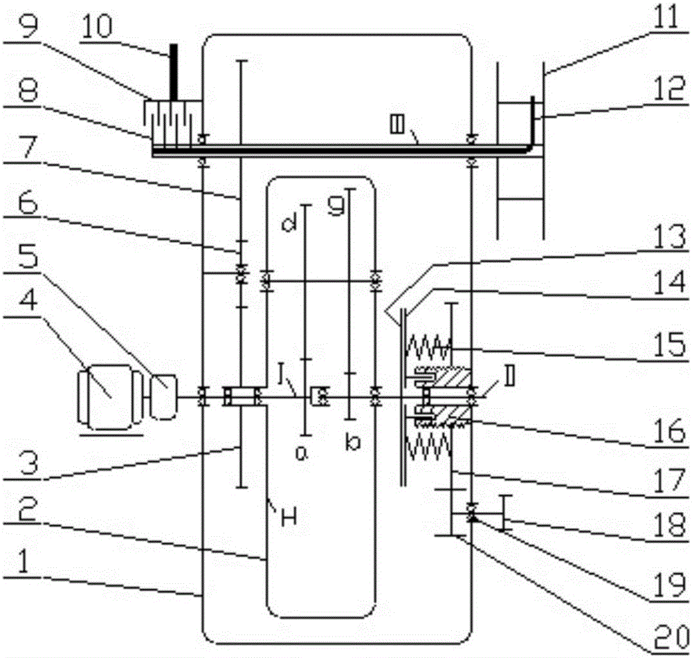
[0023] Embodiments of flexible cable reel devices, such as Figure 1-5 As shown, it includes a box body 1, a 2K-H (WW) type positive planetary differential transmission mechanism 2, a planet carrier gear 3, a motor 4, a worm gear reducer 5, a transition gear 6, a drum shaft gear 7, and a Electric appliance rotating slide 8, collector fixed slide 9, power cord 10 of mobile equipment itself, reel 11, power supply cable 12, rotating friction disc 13, moving friction disc 14, compression spring 15, adjustment seat 16, pressure plate 17, driving handle 18, bearing 19, handle gear 20. Lubricating oil is added in the box body 1 to ensure that each rotating part in the box body 1 is always in a lubricated state.

[0024] 2K-H (WW) type positive planetary differential transmission mechanism 2 is composed of input shaft I, sun gear a and sun gear b, planetary gear d and planetary gear g, planet carrier H, and speed regulating shaft. The number of teeth of sun gear a and sun gear b, pl...


PUM


Abstract

The invention relates to cable take-up equipment, in particular to a cable drum device capable of taking up a cable flexibly. The device comprises a winding drum; the winding drum is in transmission connection with a speed regulation device; the speed regulation device comprises a box body and a planet differential transmission mechanism arranged in the box body; the planet differential transmission mechanism comprises an input shaft, a speed regulation shaft and a planet carrier, which are rotationally assembled on the box body; the rotating axes of the input shaft, the speed regulation shaft and the planet carrier are in the same line; a braking mechanism is arranged between the speed regulation shaft and the box body; the planet differential transmission mechanism is in transmission connection with the winding drum through the planet carrier. When the device is in use, a driving force borne by the winding drum can be distributed by the planet differential transmission mechanism, so that the winding drum only supplies a required relatively small pulling force to the cable, a required force for taking up the cable can be regulated automatically through automatic speed change of the transmission mechanism, and the purpose of taking up the cable flexibly can be achieved. Therefore, the cable drum device capable of taking up the cable flexibly solves the problem that a conventional cable drum device damages cables.

Description

technical field [0001] The invention relates to cable retracting equipment, in particular to a cable reel device capable of flexible cable retraction. Background technique [0002] The cable reel device, as the name suggests, is mainly used for retracting and releasing cables. It is widely used to provide power supply, control power supply or control signal for mobile devices. [0003] The current cable reel device mainly includes a reel and a slipping mechanism, wherein the slipping mechanism mostly adopts a friction clutch, a hydraulic coupler, a magnetic coupler, a stall torque motor, etc., and is arranged in the reel. [0004] In use, the reel is mounted on and travels with the mobile device. When the cable is taken up, the winding speed of the reel is greater than the walking speed of the mobile device, and the sliding mechanism is used to keep the winding speed of the reel consistent with the walking speed of the mobile device, so that the cable is tensioned on the o...

Claims


Application Information

Patent Timeline
Patent Type & Authority Patents(China)
IPC IPC(8): B65H75/42B65H75/44
Inventor 李恒灿张勇牛金星张涛雷冀南
Owner NORTH CHINA UNIV OF WATER RESOURCES & ELECTRIC POWER
Why Eureka
Try Eureka