A cable take-up and release device

A cable retracting and unwinding device and cable technology, applied in the field of cable retracting and unwinding devices, can solve problems such as damage to cables, and achieve the effects of low power consumption, energy saving and compact structure

Active Publication Date: 2016-09-21
郑州天河通信科技有限公司
View PDF5 Cites 0 Cited by
  • Summary
  • Abstract
  • Description
  • Claims
  • Application Information

AI Technical Summary

Problems solved by technology

[0003] The purpose of the present invention is to provide a cable take-up and pay-off device to solve the problem that the existing take-up and take-off device cannot automatically brake when it stops and the cable is damaged by inertial operation

Method used


Image

  • A cable take-up and release device
  • A cable take-up and release device
  • A cable take-up and release device

Examples


Embodiment Construction

[0015] The present invention will be further introduced below in conjunction with the accompanying drawings and specific embodiments.

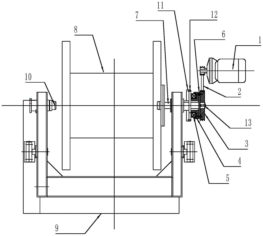
[0016] Such as figure 1 Shown is a schematic structural view of an embodiment of the cable take-up and release device of the present invention. As can be seen from the figure, the device includes a take-up and take-off tray tool 8 fixed on the support 9, and the support is provided at the corresponding position of the take-up and take-off tray tool. There is a top cone 10, and the transmission shaft 7 of the take-up and pay-off reel tool 8 is connected with the transmission motor 1 through a transmission mechanism, and a braking device is arranged between the transmission shaft 7 and the transmission mechanism.

[0017] The braking device of this embodiment is an electromagnetic clutch, which includes a stator-rotor assembly 4 of the clutch body, a coil assembly 5 and an armature assembly 6 (including a shaft sleeve). The direction of the tra...


PUM


Abstract

The invention discloses a cable take-up and pay-off device, which comprises a take-up and take-off tray equipped with a transmission shaft, the transmission shaft is connected with a transmission motor through a transmission mechanism, and a brake device is arranged between the transmission shaft and the transmission mechanism. The cable take-up and pay-off device of the present invention is equipped with a brake device between the transmission shaft of the take-up and take-off reel and the transmission mechanism. In the event of unexpected shutdown, etc., the transmission mechanism can be instantly and reliably in a static state, and can meet the operation of the transmission motor under different conditions, which effectively solves the problem of the inertial operation of the existing take-up and pay-off device that cannot automatically brake when parking The problem of cable damage can be solved, and automatic control of equipment can be realized, which has good practical effect, saves energy, and reduces operating costs.

Description

technical field [0001] The invention relates to a cable retracting and unwinding device. Background technique [0002] After the production and processing of wire and cable is completed, it usually needs to be wound on a reel to facilitate transportation and user use. Therefore, a wire take-up machine is generally required in the final process of wire and cable processing. Existing wire take-up machines generally use a motor to drive a scrolling device to drive the reel to take up the wire. This kind of wire take-up machine has the advantages of simple structure and low cost, but this kind of wire take-up and pay-off mechanism generally relies on the motor to connect the load through the pulley or the reduction mechanism. Usually, the stop of the take-up and pay-off mechanism depends on the loss of transmission torque after the motor loses power. A free stop is formed, and once the take-up and pay-off mechanism loses power during operation, it will continue to rotate due to...

Claims


Application Information

Patent Timeline
Patent Type & Authority Patents(China)
IPC IPC(8): B65H54/40
Inventor 宋广平王旭
Owner 郑州天河通信科技有限公司
Why Eureka
Try Eureka