

Swing support leg mounting structure, control device, control system, control method and engineering machinery
A technology for construction machinery and installation structures, which is applied in the direction of fluid pressure actuation devices, mechanical equipment, servo motors, etc. It can solve the problems that the outriggers cannot be fully expanded, the outriggers are not allowed to swing in a large range, and it is easy to cause tipping, etc.
- Summary
- Abstract
- Description
- Claims
- Application Information
AI Technical Summary
Problems solved by technology
Method used
Image

Examples
Embodiment Construction
[0029] Specific embodiments of the present invention will be described in detail below in conjunction with the accompanying drawings. It should be understood that the specific embodiments described here are only used to illustrate and explain the present invention, and are not intended to limit the present invention.
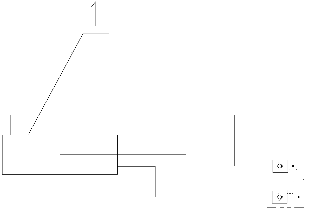
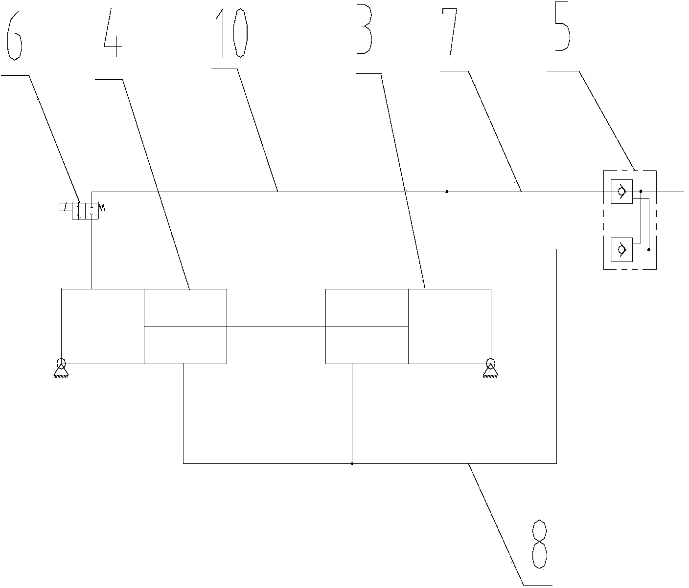
[0030] see figure 2 , according to a first aspect of the present invention, a swing leg installation structure is provided, the swing leg installation structure includes a swing leg, a body and a telescopic drive device, one end of the swing leg is hinged to the body, and the telescopic drive device is hinged to Between the swing outrigger and the body, the swing outrigger can be driven to move at least between the retracted position and the unfolded position. Specifically, the telescopic driving device includes a first driving cylinder 3 and a second driving cylinder 4 connected in series, preferably, the first driving cylinder 3 and the second driving cylind...
PUM
 Abstract
Description
Claims
Application Information