
A tool real-time detection device

A real-time detection and cutting tool technology, applied in the direction of measuring devices, material analysis through optical means, instruments, etc., can solve the problems of wasting time, inconvenient cooperation between detection tools and cutting tools, and achieve the effect of saving time

Active Publication Date: 2016-08-10
CRRC QINGDAO SIFANG CO LTD
View PDF5 Cites 0 Cited by
  • Summary
  • Abstract
  • Description
  • Claims
  • Application Information

AI Technical Summary

Problems solved by technology

[0005] The technical problem to be solved by the present invention is to solve the inconvenient cooperation between the detection tool and the cutting tool during the detection process of the cutting tool, and when the same part of the same type of cutting tool is detected many times, the detection tool needs to readjust the detection position, thus causing a waste of time.

Method used


Image

  • A tool real-time detection device
  • A tool real-time detection device

Examples


Embodiment Construction

[0020] Embodiments of the present invention will be further described in detail below in conjunction with the accompanying drawings and examples. The following examples are used to illustrate the present invention, but should not be used to limit the scope of the present invention.

[0021] In the description of the present invention, unless otherwise specified, "plurality" means two or more; unless otherwise specified, "notch-shaped" means a shape other than an even cross-section. The orientation or positional relationship indicated by the terms "upper", "lower", "left", "right", "inner", "outer", "front end", "rear end", "head", "tail" etc. is Based on the orientation or positional relationship shown in the drawings, it is only for the convenience of describing the present invention and simplifying the description, and does not indicate or imply that the referred device or element must have a specific orientation, be constructed and operated in a specific orientation, and th...


PUM


Abstract

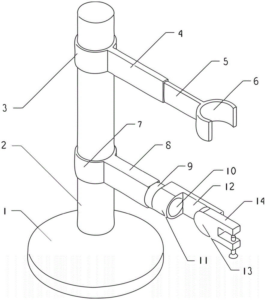
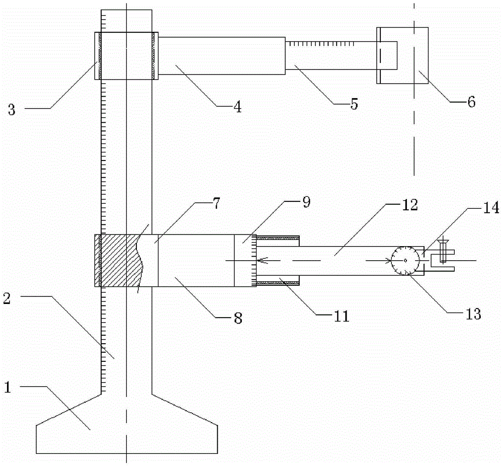
The invention relates to the technical field of machining, particularly to a real-time cutter detection device. A support rod is fixed on a base of the real-time cutter detection device, and a tool clamping mechanism and a cutter clamping mechanism are rotationally connected onto the support rod and capable of moving in the axial direction of the support rod. According to the real-time cutter detection device, through the rotation or movement of the tool clamping mechanism and the cutter clamping mechanism, detection tools such as a handheld microscope and the like can be fixed conveniently, and detection positions can be recorded easily when cutting edges of cutters are detected, so that the device can be easily adjusted to appropriate positions for detection when identical parts of the cutting edges of the cutters or cutting edges of other cutters in the same types are detected next time, and the time is saved.

Description

technical field [0001] The invention relates to the technical field of machining, in particular to a tool real-time detection device. Background technique [0002] At present, in the field of mechanical processing such as turning, milling and other processing processes, it is inevitable to use a variety of cutting tools, and in the process of using the cutting tools, there will be various damages such as wear and tear. It is necessary to ensure that For the smooth progress of the machining process, it is necessary to ensure that the damage of the tool within its life cycle cannot exceed the allowable range, that is, during the machining process, the tool must be tested in real time to ensure that it can meet the processing requirements. [0003] Now the commonly used tool detection method is to remove the tool and put it on a platform, and then move the detection tool such as a hand-held microscope to detect the tool. Using this method is not only inconvenient for the detect...

Claims


Application Information

Patent Timeline
Patent Type & Authority Patents(China)
IPC IPC(8): G01N21/84
Inventor 李世涛邓小军刘韶庆赵彦华于鑫张占岭张世欣
Owner CRRC QINGDAO SIFANG CO LTD
Learn More