
Electrical conductor splicing device

A technology for splicing electric wires, applied in the field of splicing devices for electric wires, which can solve the problems of increased resistance, weak joints, and heat generation of joints, and achieves the effects of simple structure, simple and portable device, and fast twisting speed

Active Publication Date: 2015-12-09
CSCEC STRAIT CONSTR & DEV
View PDF6 Cites 0 Cited by
  • Summary
  • Abstract
  • Description
  • Claims
  • Application Information

AI Technical Summary

Problems solved by technology

These defects lead to insufficient contact surface between wires, which may easily lead to quality problems such as joints are not firm, joints heat up, and resistance increases.

Method used


Image

  • Electrical conductor splicing device
  • Electrical conductor splicing device
  • Electrical conductor splicing device

Examples


Embodiment Construction

[0016] The content of the present invention will be described in detail below in conjunction with the accompanying drawings and embodiments of the description:

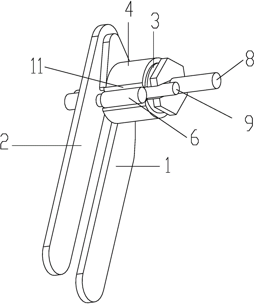
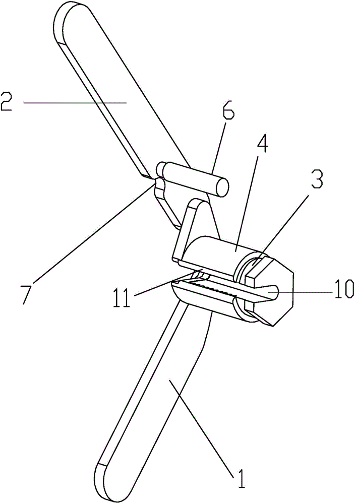
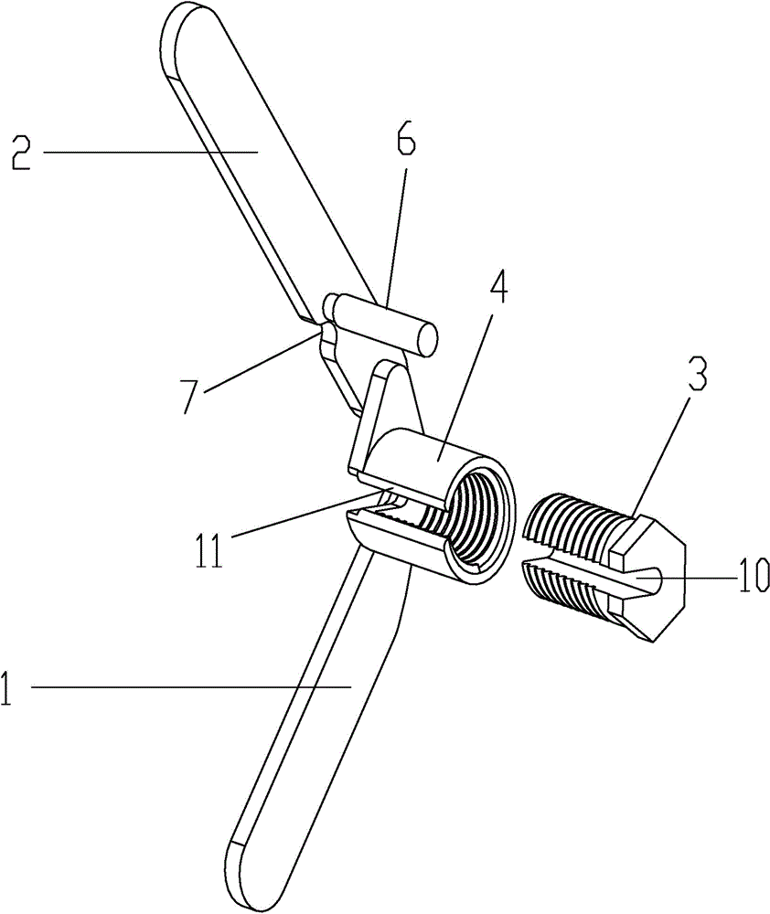
[0017] An electric wire splicing device, which includes a rotating rod sleeve 4 sealed at the left end and a rotating rod 3 nested in the rotating rod sleeve 4 and rotatingly matched with the rotating rod sleeve 4 through a thread structure; the rotating rod 3 is provided with The wire accommodating groove 10 of the rotating rod 3 is penetrated axially, and the wire receiving opening 11 corresponding to the wire accommodating groove 10 is provided on the rotating rod sleeve 4 . When the two wires to be spliced ​​are put into the wire accommodating groove 10 through the wire insertion opening 11, the axis of the wire A8 near or against the bottom of the wire accommodating groove 10 is coaxial with the rotation axis of the rotating rod 3, and the wire B9 Place it close to wire A8.

[0018] The invention can not only re...


PUM


Abstract

The invention relates to an electrical conductor splicing device which comprises a rotating rod sleeve and a rotating rod, wherein the left end of the rotating rod sleeve is sealed; the rotating rod is nested in the rotating rod sleeve and is in running fit with the rotating rod sleeve by a screw thread structure; the rotating rod is provided with a conductor accommodating groove axially running through the rotating rod; and the rotating rod sleeve is provided with a conductor placement inlet corresponding to the conductor accommodating groove. The invention aims to provide the electrical conductor splicing device which is portable and is easy to operate. The electrical conductor splicing device has the advantages that 1, the device disclosed by the invention is simple and portable and has a high splicing speed, work efficiency is improved and the electrical conductor splicing device has obvious economic benefits; and 2, the electrical conductor splicing device has a simple structure and low price and is helpful to popularization and application.

Description

technical field [0001] The invention relates to a splicing device for electric wires, in particular to a splicing device which can be used for branches of electric wires. Background technique [0002] In the construction of building electrical engineering, the splicing method should be adopted for the branch connection of the wires: strip the insulation sheath of the wires to expose the metal conductors, and splice them manually. The spliced ​​wires should be tightly wrapped with the straight wires, and the number of twisted turns is 6. ~8 laps. Because the hardness of the wires is strong and there is no special splicing tool, the connection of the wires is all manual splicing, which takes a long time and is laborious. Restricted by the technical level and sense of responsibility of the operators, wire splicing often has defects such as loose splicing turns, insufficient splicing grip, and insufficient number of splicing turns. These defects lead to insufficient contact su...

Claims


Application Information

Patent Timeline
Patent Type & Authority Patents(China)
IPC IPC(8): H01R4/12
Inventor 吴志鸿徐洪广刘火生
Owner CSCEC STRAIT CONSTR & DEV
Learn More