
Processing method and device based on projected image

A technology of projected images and processing methods, applied in the field of image processing, can solve the problems of large projection deformation, distortion of projected images, increase of uncertainty factors, etc.

Active Publication Date: 2014-03-26
HUAWEI TECH CO LTD
View PDF6 Cites 26 Cited by
  • Summary
  • Abstract
  • Description
  • Claims
  • Application Information

AI Technical Summary

Problems solved by technology

Traditional projection displays generally use ceiling-mounted or table-mounted fixed settings, and have a fixed projection surface. With the development of technology, projectors are getting smaller and smaller and can be moved freely and flexibly, such as wearable projection devices. It can be configured on the human body, which increases the uncertainty factors in the projection environment. The angle change between the projection device and the projection surface and the unevenness of the projection surface will cause the projection image to be distorted. How to deal with this image distortion is particularly important. important
The prior art provides a projection device, including a projector, a projection surface, and a camera. The projector projects an interactive interface on a certain medium, and the user interacts with the interface through a specific gesture, which is captured and transmitted by the camera. The computing device recognizes and drives the device to complete corresponding actions according to the recognition results. However, since the specific location of the projection surface is not known in advance, the angle between the projector and the projection surface may change frequently. This complex projection environment will cause the projected image Generate large projection deformation and distort the displayed image

Method used


Image

  • Processing method and device based on projected image
  • Processing method and device based on projected image
  • Processing method and device based on projected image

Examples


Embodiment 2

[0247] An embodiment of the present invention provides a processing device based on projected images, such as Image 6 As shown, the device includes:

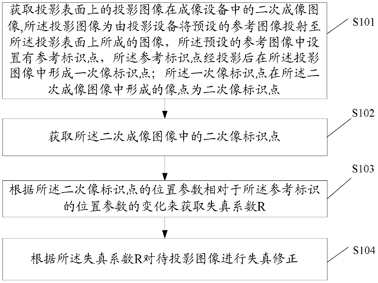
[0248] The imaging acquisition unit 301 is configured to acquire a secondary imaging image of the projection image on the projection surface in the imaging device, the projection image is an image formed by projecting a preset reference image onto the projection surface by the projection device, A reference marker point is set in the preset reference image, and the reference marker point forms a primary image marker point in the projected image after projection; the primary image marker point is formed in the secondary imaging image The image point is the secondary image identification point;

[0249] An image identification point acquisition unit 302, configured to acquire a secondary image identification point in the secondary imaging image;

[0250] The distortion coefficient acquisition unit 303 is configured to obtain th...


PUM


Abstract

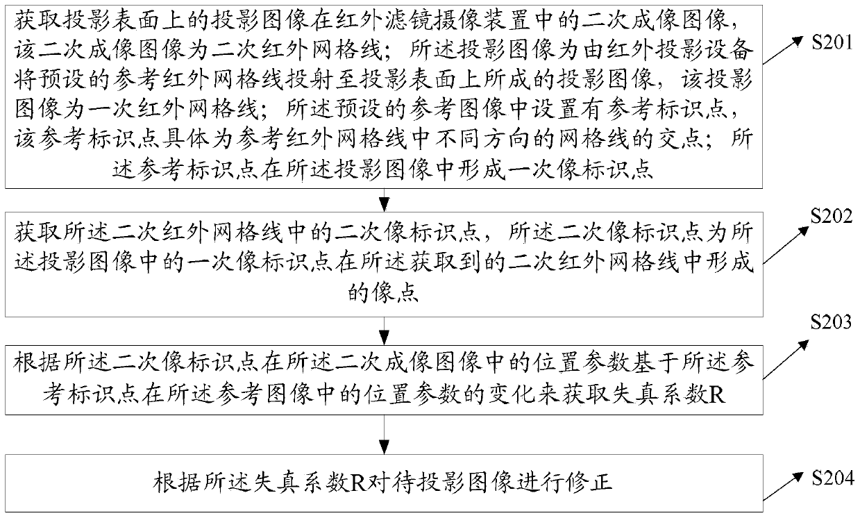
The invention belongs to the technical field of image processing, and provides a processing method and device based on a projected image. The method comprises the steps that a secondary imaged image of the projected image on a projection surface is obtained, wherein the projected image is formed by projecting a preset reference image on the projection surface, and reference identification points are preset in the reference image; secondary image identification points in the secondary imaged image are obtained; a distortion factor is obtained according to the change of the position parameters of the secondary image identification points in the secondary imaged image based on the position parameters of the reference identification points in the reference image; an image to be projected is corrected according to the distortion factor. Processed projected images are made to be reduced in distortion or even be free of distortion, and thus the environment adaptive capacity of image projecting equipment is improved.

Description

technical field [0001] Embodiments of the present invention relate to the field of image processing, and in particular, to a projection image-based processing method and device. Background technique [0002] Projection display is a display method widely used in people's daily work and life. It is loved by the public for its adjustable size of projected image, free and flexible selection of projected surface, and free mobility of projected equipment. . Traditional projection displays generally use ceiling-mounted or table-mounted fixed settings, and have a fixed projection surface. With the development of technology, projectors are getting smaller and smaller and can be moved freely and flexibly, such as wearable projection devices. It can be configured on the human body, which increases the uncertainty factors in the projection environment. The angle change between the projection device and the projection surface and the unevenness of the projection surface will cause the p...

Claims


Application Information

Patent Timeline
IPC IPC(8): H04N9/31G06T5/00
CPCH04N9/3194H04N9/3185
Inventor 许春景黎伟刘健庄
Owner HUAWEI TECH CO LTD
Learn More