Landscape decorative lamp system and address coding and display control method thereof
A technology of address coding and decorative lights, which is applied to lighting devices, lamp circuit layout, light sources, etc., and can solve problems such as decorative lights not working properly and driver chips failing
- Summary
- Abstract
- Description
- Claims
- Application Information
AI Technical Summary
Problems solved by technology
Method used
Image
Examples
Embodiment 1
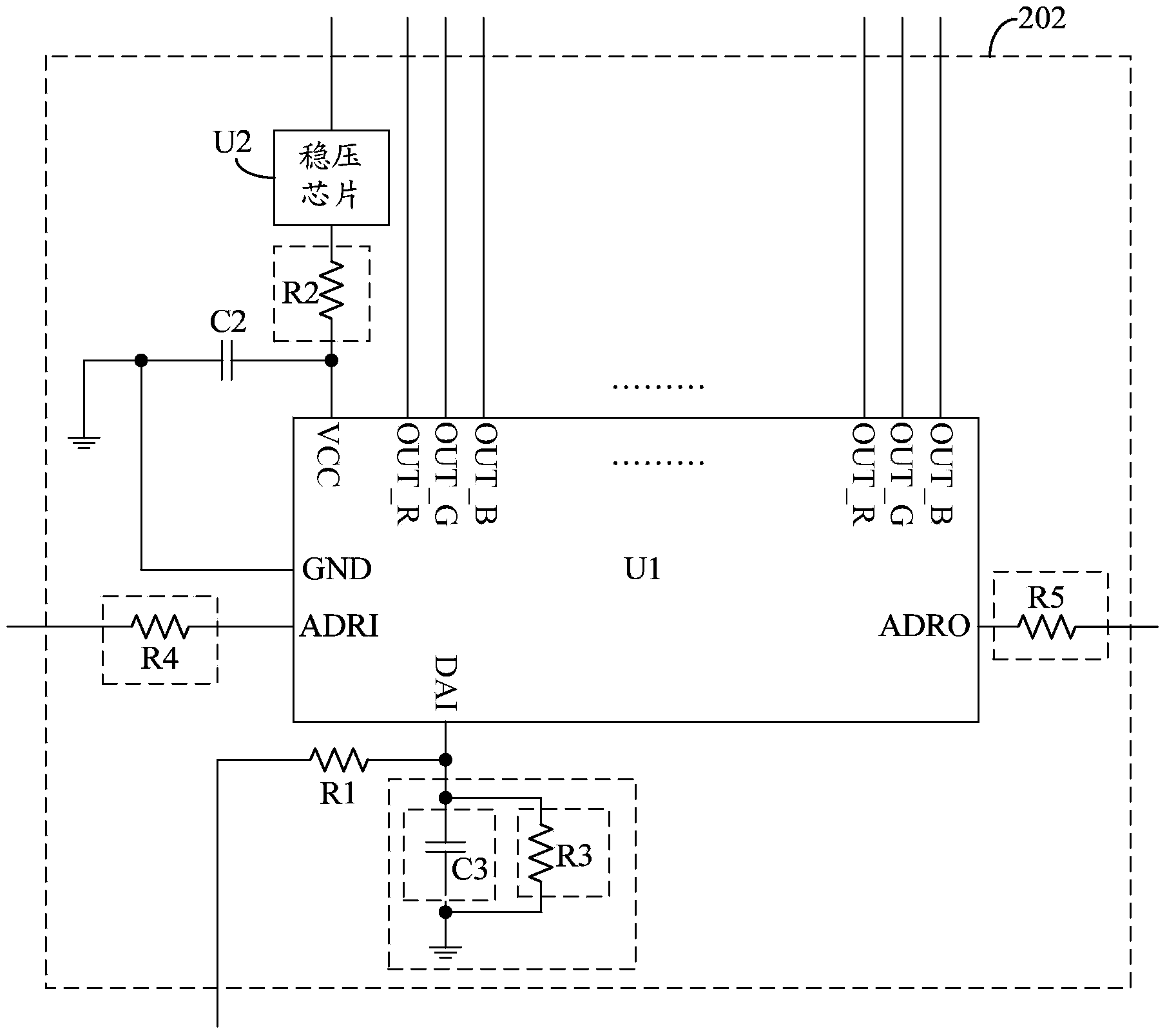
[0054] Such as image 3 As shown, the main control module 202 includes:
[0055] Main control chip U1, voltage regulator chip U2, second capacitor C2 and first resistor R1;
[0056] The input end of the voltage stabilizing chip U2 is used as the power supply end of the main control module 202, the output end of the voltage stabilizing chip U2 and the first end of the second capacitor C2 are connected to the power supply pin VCC of the main control chip U1, and the first end of the second capacitor C2 The two ends are connected to the ground together with the ground pin GND of the main control chip U1, the address input pin ADRI of the main control chip U1 is the address input end of the main control module 202, and the first end of the first resistor R1 is connected to the data of the main control chip U1 The input pin DAI, the second terminal of the first resistor R1 is the display data terminal of the main control module 202, and the output pins (OUT_R, OUT_G, OUT_B) of the...
Embodiment 2
[0069] Such as Figure 5 As shown, the main control module 202 includes:
[0070] Main control chip U1, voltage regulator chip U2, second capacitor C2, first resistor R1 and second resistor R2;
[0071] The input end of the voltage stabilizing chip U2 is used as the power supply end of the main control module 202, the output end of the voltage stabilizing chip U2 and the first end of the second capacitor C2 are connected to the power supply pin VCC of the main control chip U1, and the first end of the second capacitor C2 The two ends are connected to the ground together with the ground pin GND of the main control chip U1, the address input pin ADRI of the main control chip U1 is the address input end of the main control module 202, the first end of the first resistor R1 and the second end of the second resistor R2 One end is respectively connected to the first data input pin DAI_A and the second data input pin DAI_B of the main control chip U1, the second end of the first res...
Embodiment 3
[0081] Such as Figure 7 As shown, the main control module 202 includes:
[0082] Main control chip U1, second capacitor C2, first resistor R1 and second resistor R2;
[0083] The first terminal of the first resistor R1 is used as the power supply terminal of the main control module 202, the second terminal of the first resistor R1 and the first terminal of the second capacitor C2 are connected to the power supply pin VCC of the main control chip U1, and the second capacitor C2 The second end of the resistor R2 is connected to the ground together with the ground pin GND of the main control chip U1, the address input pin ADRI of the main control chip U1 is the address input end of the main control module 202, and the first end of the second resistor R2 is connected to the main control chip U1 The data input pin DAI of the second resistor R2, the second terminal of the second resistor R2 is the display data terminal of the main control module 202, and the output pins (OUT_R, OU...
PUM
 Abstract
Description
Claims
Application Information
 - R&D
- Intellectual Property
- Life Sciences
- Materials
- Tech Scout
- Unparalleled Data Quality
- Higher Quality Content
- 60% Fewer Hallucinations
Browse by: Latest US Patents, China's latest patents, Technical Efficacy Thesaurus, Application Domain, Technology Topic, Popular Technical Reports.
© 2025 PatSnap. All rights reserved.Legal|Privacy policy|Modern Slavery Act Transparency Statement|Sitemap|About US| Contact US: help@patsnap.com


