Portable power source type track laying machine for subway construction

A technology of mobile power supply and laying machine, which is applied in the direction of track, track maintenance, track laying, etc. It can solve the problems that affect the construction progress, increase the cost of equipment use, and burn the motor rotor coil, so as to save labor and improve the passing capacity.

Pending Publication Date: 2017-11-07
CHINA RAILWAY FIRST GRP CO LTD +1
View PDF5 Cites 9 Cited by
  • Summary
  • Abstract
  • Description
  • Claims
  • Application Information

AI Technical Summary

Problems solved by technology

[0004] When using traditional track laying machines to lay tracks in long sections, such as long-distance sea-crossing bridges and tunnels that appear in coastal urban rail transit networks, due to the need for starting torque of the motor, the current that needs to be absorbed from the grid is 6-6% of the rated current of the motor 7 times. Excessive starting current not only wastes power, but also greatly damages the voltage fluctuation of the power grid. In addition, due to the long power supply line and large resistance required for track laying in the long section, the voltage drop at the moment of motor startup is large. When the voltage drop When it exceeds the allowable voltage drop range of the motor, it will cause the motor to fail to operate normally or even burn the motor
Although the existing mature technology solves the voltage drop problem by installing booster and voltage regulator equipment in long-distance power supply lines, the effect is limited and the cost performance is not high
[0005] 2. Broken core, hang-up and rolling-off problems of coiled cables
[0006] The power receiving line of traditional track laying machine generally uses rubber sheath flexible cable as the power receiving coil cable. In order to reduce the number of switching power interface as much as possible and improve construction efficiency during daily track laying and pouring construction, each track laying machine is generally equipped with The length of the coiled cable is 150m. Since the coiled cable is too long, frequent rewinding and unwinding of the coiled cable will easily cause the cable to break and lose phase, which will cause the motor rotor coil to burn out and affect the construction. Because the broken core of the cable cannot be determined from the appearance It takes a long time to check and repair the broken core
During the construction, due to human and environmental factors such as high work intensity of the operator, insufficient lighting on site, and many sundries embedded in the tunnel surface, the coiled cable wires were often hung up or rolled off, causing electric shocks or frequent tripping failures. During construction, the insulation drop of the repaired coiled cable will also cause electric shock or frequent trips. After the repair, the coiled cable will be replaced every one or two months on average, which not only seriously affects the construction progress, but also poses safety hazards. , also increases the cost of equipment use
[0007] 3. The problem of low efficiency of switching power interface
[0008] Because the length of the cable that can be coiled by the track laying machine is limited, the power interface needs to be replaced frequently during long-distance transportation. Manually replacing the power interface requires a series of processes such as unwiring, pulling, and wiring, and the workload and labor intensity are large. , and the work efficiency is low
[0009] 4. In order to ensure the normal construction of the track laying machine, the power supply line that provides power for the traditional track laying machine should be laid along the construction line, and the labor and time costs required for laying the power supply line should be paid. At the same time, in order to ensure the working voltage of the track laying machine, To reduce the electrical resistance of the power supply line along the construction line, it is necessary to increase the cable section of the power supply line laid along the track laying construction, resulting in an increase in the cost of power supply line materials

Method used


Image

  • Portable power source type track laying machine for subway construction
  • Portable power source type track laying machine for subway construction
  • Portable power source type track laying machine for subway construction

Examples


Embodiment Construction

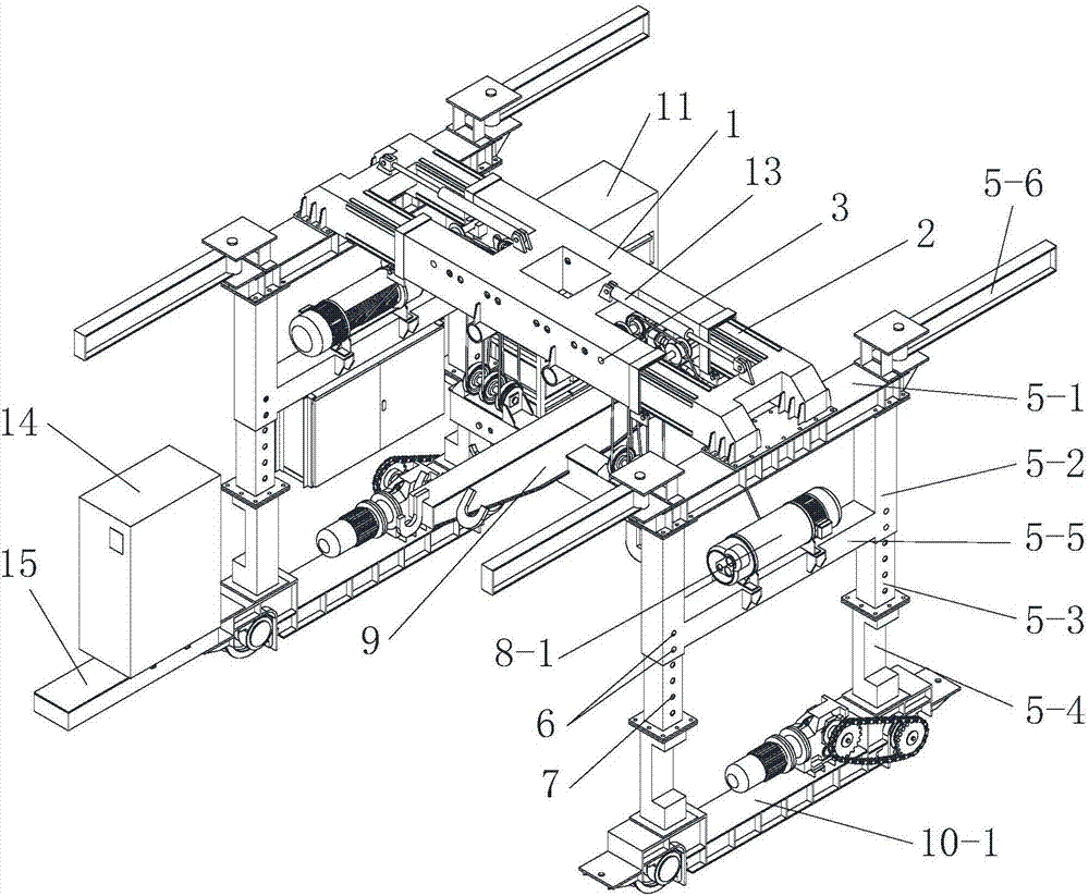
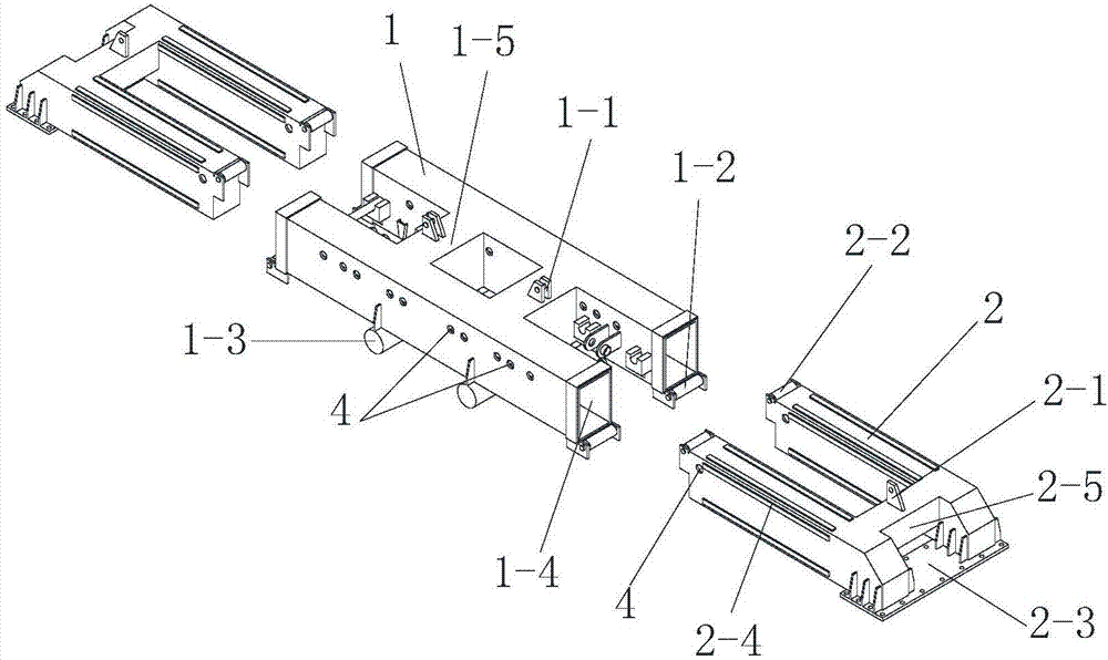
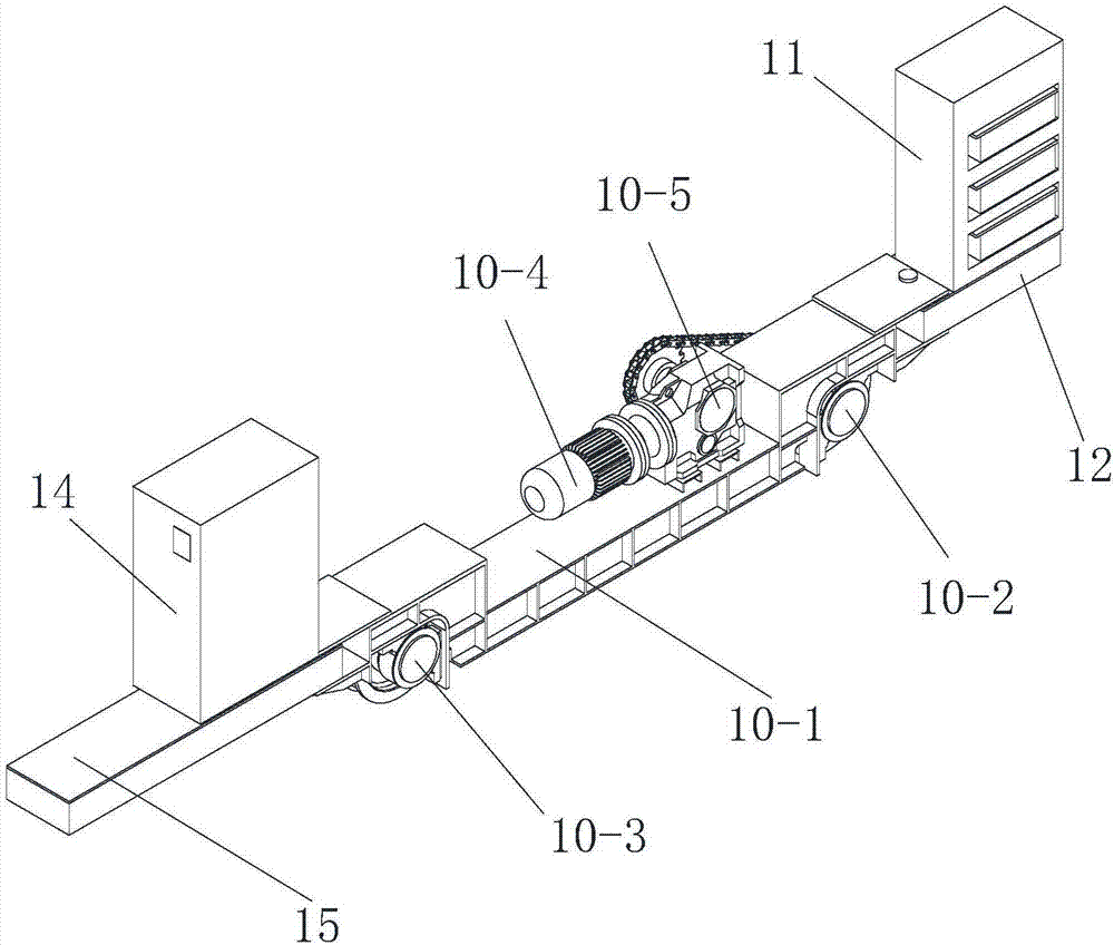
[0049] Such as figure 1 , figure 2 and image 3 As shown, the present invention includes a portal bracket, a lifting device installed on the portal bracket and a running device for driving the portal bracket to move back and forth, and also includes a lifting device installed on the portal bracket or the running device The mobile power supply 11, the portal bracket includes a main beam and two height-adjustable outriggers respectively installed under both sides of the main beam, and the main beam is composed of a straight beam 1 and two left and right sides of the straight beam 1. The telescopic beam 2 is composed of a telescopic beam 2 at the end, the telescopic beam 2 has a plug-in end and a fixed end, the plug-in end of the telescopic beam 2 is installed inside the straight beam 1, and the fixed end of the telescopic beam 2 is fixedly installed on the On the top of the height-adjustable outrigger, the straight beam 1 is provided with a variable-span driving mechanism for...


PUM


Abstract

The invention discloses a portable power source type track laying machine for subway construction. The track laying machine comprises a door type support, a lifting device, a traveling device and a portable power source, wherein the lifting device is installed on the door-type support, the traveling device is used for driving the door type support to move forwards and backwards, and the portable power source is installed on the door type support or the traveling device. The door type support comprises a main beam and two height-adjusting supporting legs, wherein the two height-adjusting supporting legs are installed on the lower portions of the two sides of the main beam respectively; the main beam comprises a straight beam body and telescopic beam bodies, wherein the telescopic beam bodies are connected to the left end and the right end of the straight beam body in an inserted mode respectively. Each telescopic beam body is provided with an inserting connection end and a fixed end, the inserting connection ends of the telescopic beam bodies are installed in the straight beam body, and the fixed ends of the telescopic beam bodies are fixedly installed on the tops of the height-adjusting supporting legs. In the portable power source type track laying machine, the portable power source is used as a power source of the laid track, in the long and large section laying process, it is only required that the portable power source is changed, it is not required that power supply interfaces are changed many times, and coiling cables do not need to be deployed and retracted frequently, the manpower, machines and tools, materials and time cost required for laying and constructing the power source are saved.

Description

technical field [0001] The invention belongs to the technical field of subway construction, and relates to a subway track laying construction equipment, in particular to a mobile power supply type track laying machine for subway construction. Background technique [0002] The track laying machine for subway construction is the key equipment for the "machine-laying method" construction of the subway track. It is responsible for transporting the prefabricated rail rows, steel cages, and pre-accompanied concrete to the construction site in the direction of track laying, and gradually completes track laying and pouring. construction tasks. At present, the traditional power supply mode has the following problems in actual construction: [0003] 1. The problem of power supply voltage drop [0004] When using traditional track laying machines to lay tracks in long sections, such as long-distance sea-crossing bridges and tunnels that appear in coastal urban rail transit networks, ...

Claims


Application Information

Patent Timeline
Patent Type & Authority Applications(China)
IPC IPC(8): E01B29/02H02J7/00
CPCH02J7/00E01B29/02
Inventor 张峰杨铖李育朝刘佳王斌杨帆王红刚王伟
Owner CHINA RAILWAY FIRST GRP CO LTD
Why Eureka
Try Eureka