A radar three-dimensional imaging method and system based on the tangent envelope surface of an ellipsoid

A technology of three-dimensional imaging and envelope surface, which is applied in radio wave measurement system, radio wave reflection/re-radiation, utilization of re-radiation, etc., can solve the problem of low accuracy of object boundary shape restoration, which is unfavorable for real-time imaging applications, imaging Recognition effects and other issues can be achieved to achieve real-time applications, improve imaging speed, imaging accuracy, and strong noise resistance

Active Publication Date: 2016-01-20
GUILIN UNIV OF ELECTRONIC TECH
View PDF5 Cites 0 Cited by
  • Summary
  • Abstract
  • Description
  • Claims
  • Application Information

AI Technical Summary

Problems solved by technology

However, such methods are not conducive to the application of real-time imaging due to the large amount of calculation
At the same time, the accuracy of restoring the boundary shape of the target is not high, so the imaging recognition is also affected to a certain extent

Method used


Image

  • A radar three-dimensional imaging method and system based on the tangent envelope surface of an ellipsoid
  • A radar three-dimensional imaging method and system based on the tangent envelope surface of an ellipsoid
  • A radar three-dimensional imaging method and system based on the tangent envelope surface of an ellipsoid

Examples


Embodiment Construction

[0024] The present invention will be further described in detail below in conjunction with the accompanying drawings and embodiments.

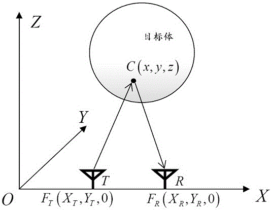
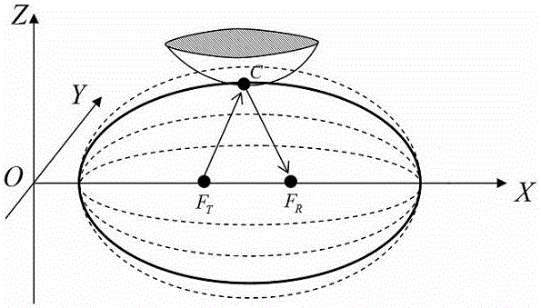
[0025] The coordinates of the transmitting and receiving antennas are F T (X T ,Y T ,0) and F R (X R ,Y R ,0), the electromagnetic wave propagates to the target through the transmitting antenna and then reflects back to the receiving antenna. Suppose the electromagnetic wave is reflected at the boundary point C(x,y,z) of the target body, then the electromagnetic wave path is F T (X T ,Y T ,0)→C(x,y,z)→F R (X R ,Y R ,0), that is, the path length of the electromagnetic wave reflected from the transmitting antenna to the target and then reflected back to the receiving antenna can be expressed as R=|F T C|+|CF R |, such as figure 1 shown. The coordinates of the transmitting antenna and the receiving antenna F T (X T ,Y T ,0) and F R (X R ,Y R ,0) as the two focus coordinates of an ellipse, whose focal length is |X T -X R |. ...


PUM


Abstract

The invention discloses a radar three-dimensional imaging method and a system based on an ellipsoid tangent point envelope surface. The method comprises the following steps : dividing a transmitting-receiving antenna; moving the transmitting-receiving antenna by an interval in m*n antenna coordinate matrix scanning domains at a delta t time interval to obtain m*n groups of electromagnetic echo data; respectively taking a transmitting-receiving antenna coordinate as an elliptic focus, a target body reflection echo path length as an elliptical major axis and constructing m*n ellipses and respectively obtaining each elliptical semi-minor axis; constructing m*n ellipsoids to form an ellipsoid set by using an ellipsoid equatorial radius which takes an elliptical semi-major axis as the axis X and the axis Y and an ellipsoid polar radius which takes the elliptical semi-minor axis as the axis Z; constructing an envelope surface which is tangent to each ellipsoid of the ellipsoid set, selecting the envelope surface which envelopes a tangent point in the maximum axis Z direction, and in the envelope surface which envelopes the tangent point in the maximum axis Z direction, taking the envelope surface composed of geometric centers in any of all of the adjacent four adjacent tangent points as a target body boundary to realize imaging. The method and the system disclosed by the invention have strong anti-noise property, can improve the imaging speed and accuracy, and satisfy requirements of real-time application.

Description

technical field [0001] The invention relates to the technical field of radar imaging, in particular to a radar three-dimensional imaging method and system based on an ellipsoid tangent envelope surface. Background technique [0002] At present, the theoretical framework of radar two-dimensional imaging technology has matured. However, two-dimensional imaging can only restore the cross-sectional shape of the target object, and cannot image and reconstruct the whole object, resulting in a low degree of object recognition by the radar system. Therefore, radar 3D imaging technology has become a hot and difficult research topic for domestic and foreign scholars in recent years. Different from 2D imaging, 3D imaging needs to consider the three parameters of distance-azimuth-pitch of the target. In terms of data processing, the coordinate axis representing the height is added to reconstruct the target body, which must be extended to the area array antenna or the equivalent array o...

Claims


Application Information

Patent Timeline
Patent Type & Authority Patents(China)
IPC IPC(8): G01S13/89G01S7/41
CPCG01S7/41G01S13/89
Inventor 欧阳缮李育晖谢跃雷晋良念刘庆华蒋俊正陈紫强肖海林李民政
Owner GUILIN UNIV OF ELECTRONIC TECH
Why Eureka
Try Eureka