Sanding room dust removal cabinet

A technology of grinding room and dust removal chamber, which is applied to the separation of dispersed particles, chemical instruments and methods, combined devices, etc., can solve the problem of difficult removal of sediment, and achieve the effect of high degree of automation, high dust removal efficiency and reasonable structure layout.

Active Publication Date: 2015-05-20
江西柏司得环保设备有限公司
View PDF6 Cites 1 Cited by
  • Summary
  • Abstract
  • Description
  • Claims
  • Application Information

AI Technical Summary

Problems solved by technology

[0003] The purpose of the present invention is to provide a dust removal cabinet for a grinding room. By arranging a multi-stage filter device in the dust removal cabinet for the grinding room, the dust filtering ability of the dust removal cabinet for the grinding room can be improved, and the production environment of the grinding room can be improved; The sediment removal device is installed to solve the problem that the sediment in the cabinet is not easy to remove

Method used


Image

  • Sanding room dust removal cabinet
  • Sanding room dust removal cabinet
  • Sanding room dust removal cabinet

Examples


Embodiment 1

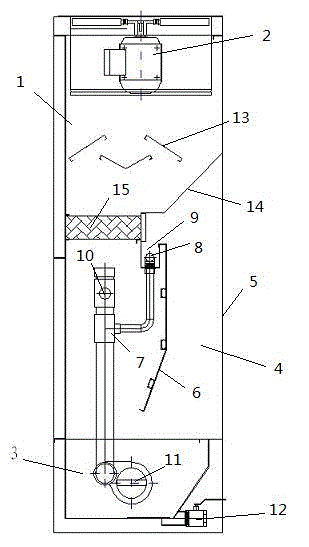
[0025] Such as figure 1 As shown, a dust removal cabinet for a grinding room includes a cabinet body 1 and a control device, the cabinet body has a top wall, side walls and a base, the top wall is provided with a fan 2, and a water tank 3 is provided above the base, The cabinet body 1 has a dust removal chamber 4 .

[0026] The dust removal chamber 4 is formed by a base, a part of side walls and a partition device arranged in the cabinet body 1 . One side of the dust removal chamber 4 of the cabinet 1 is provided with a dust suction port 5. Preferably, the dust removal chamber 4 can be set as an open chamber, that is, the dust suction port 5 is connected to the entire side of the dust removal chamber. The walls are the same size.

[0027] The dust removal chamber 4 is provided with a two-stage filter device and a water supply system for providing water to the filter device. The first-stage filter device is a vertically arranged water curtain filter device, which is compose...

Embodiment 2

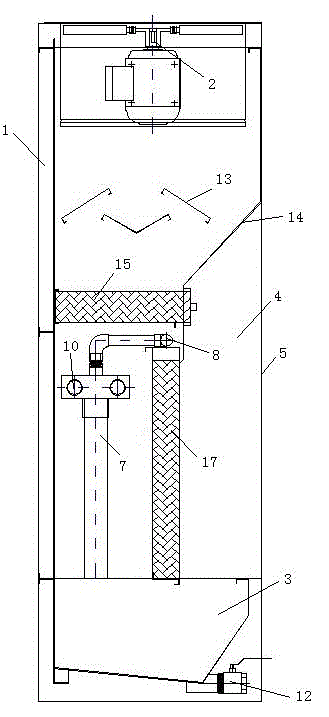
[0034] Such as figure 2 As shown, in embodiment 2, the deflector 6 in the water curtain filter device in embodiment 1 is replaced by a filter paper dust removal wall 17, and the filter paper dust removal wall 17 is a gas permeable wall formed by bending and bonding several pieces of filter paper . In this embodiment, the water outlet 8 can be directly placed on the top of the filter paper dust removal wall 17, and the water flowing out through the water outlet 8 flows down from the top of the filter paper dust removal wall 17 along the wall to form a water curtain.

[0035] All the other are with embodiment 1.

Embodiment 3

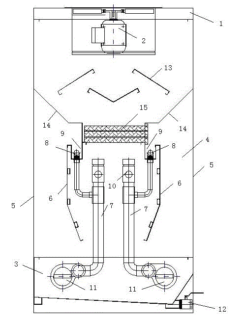
[0037] Such as image 3As shown, in embodiment 3, the dust removal chamber 4 in embodiment 1 is arranged as a double-sided symmetrical structure. Specifically, the two symmetrical sides of the dust removal chamber 4 are provided with dust suction ports 5, water curtain filter, water The mist filtering device and the water supply system are arranged symmetrically in the dust removal chamber, an airtight baffle 14 is arranged above the two water curtain filtering devices, and a filter paper dust removing device 15 is arranged above the water mist filtering device.

[0038] All the other are with embodiment 1.

[0039] The dust removal cabinet for the grinding room with such a symmetrical structure realizes simultaneous dust removal on both sides of the cabinet body, further enhancing the dust removal efficiency of the dust removal cabinet for the grinding room.


PUM


Abstract

The invention relates to a sanding room dust removal cabinet. The sanding room dust removal cabinet comprises a cabinet body and a control device, wherein the cabinet body is provided with a top wall, a side wall and a base, the top wall is provided with a fan, a water accumulation tank is arranged above the base, the cabinet body is provided with a dust removal chamber, the dust removal chamber is formed by the base, partial side wall and a separation device which is arranged in the cabinet body, a filter device is arranged in the dust removal chamber, the side wall of the dust removal chamber is provided with a dust absorption port, the filter device consists of a primary filter device and a secondary filter device, the primary filter device is a water-curtain filter device, the secondary filter device is a water mist filter device, a water supply system for supplying a water source to the filter device is arranged in the dust removal chamber, and a precipitate discharging device is arranged in the water accumulation tank. By adopting the sanding room dust removal cabinet, the dust can be thoroughly filtered, the filter intensity is high, and the dust removal efficiency is also high.

Description

technical field [0001] The invention relates to a dust removal cabinet for a grinding room, in particular to a dust removal cabinet for a grinding room with a multi-stage filtering device. Background technique [0002] Chinese utility model patent ZL201220265126.8 discloses a vacuum cabinet for a grinding room, which includes a cabinet body, a water curtain filter, a fan, a water storage tank, and an electrical control box. device and a partition plate, the overflow tank is located at the top of the filter device, the water pump communicates with the overflow tank through a water pipe, a partition plate is installed on the top of the rear side of the filter device and above the water pipe, and the rear of the cabinet A baffle is provided, and a water accumulation tank is arranged under the baffle, and the water accumulation tank is divided into two parts by the baffle, the front part is a water outlet tank, and the rear part is a decontamination tank, and a water pump is ins...

Claims


Application Information

Patent Timeline
Patent Type & Authority Patents(China)
IPC IPC(8): B01D50/00
Inventor 杨建平
Owner 江西柏司得环保设备有限公司
Why Eureka
Try Eureka